
Controlling a DC motor with Arduino
Introduction — controlling a DC motor with Arduino (for school use)
In this short introductory section we present the basic concepts and parts needed to control a DC motor with Arduino through an H-bridge driver. The focus is on school use — simple, safe and repeatable in the classroom. Before building the real circuit, we first test it and draw the schematic in TinkerCAD (or a similar simulator), and only then transfer it to real hardware.
Why an H-bridge?
A DC motor needs to be able to change its direction of rotation (forward / backward) and its speed (PWM). An H-bridge reverses the polarity of the motor supply — this is the basic function we use to control the direction.
Two popular options are often used in school projects:
- L293D — a small, simple “quad half-H” IC (or a ready-made board based on the L293D). Suitable for small DC motors (up to ~600 mA per output), easy to use, with built-in protection diodes (depending on the version). Ideal for learning and small school projects.
- L298N — a more robust dual H-bridge (often as a module with terminals and a regulator). It can handle larger currents (typically up to ~2 A continuously with a suitable heat sink) and is usually used for bigger motors and heavier vehicles. The L298N module often comes with extra components (screw terminals, 5V regulator, diodes), so it is practical for vehicle prototypes.
Key differences (summary):
- Current: L293D — better for small currents (school motors), L298N — for larger currents (heavier vehicles / bigger motors).
- Heat dissipation: the L298N handles heat better with a heat sink; the L293D may require careful temperature monitoring.
- Modules: L298N modules often come with extra terminals and a 5V regulator, which makes wiring easier but takes up more space.
This lesson: what we will do
- First: build a simple schematic and test it in TinkerCAD (simulation), so students can see how the motor and the signals behave without any risk. - Then: transfer the same schematic to real hardware and explain safety and wiring details. - Later in the course: add a second DC motor and combine both into a simple steerable vehicle (in that lesson we will also consider the L298N module for more power if needed).
List of basic parts (school kit)
- Arduino (Uno / Nano / Mega) — generates the PWM and logic signals (IN/EN).
- H-bridge driver (e.g. an L293D module or an L298N module) — chosen according to the motor current.
- DC motor — school motors (e.g. type 130/200/370) or small gear motors for vehicles.
- Jumper wires and breadboard — for prototyping (or screw terminals for permanent connections).
- External power supply for the motor — a battery or adapter (e.g. 6–12 V, depending on the motor). Do not power the motor from the Arduino 5V pin.
- Common ground (GND) — required: the GND of the motor supply and the GND of the Arduino must be connected.
- Capacitor (100 µF or more) — close to the motor supply terminals, to reduce voltage spikes.
- Protection — fuses / thermal protection for stronger motors; a heat sink for the L298N if needed.
- Optional: encoders, switches, potentiometers (for speed control), LED indicators, and a small board with screw terminals for the motor supply.
Key notes for the classroom (safety and good practice)
- Always test in the simulator first (TinkerCAD) — students will understand the signals without the risk of a short circuit.
- Do not power the motor from the Arduino 5V pin – use a separate supply (battery / adapter) that is strong enough for the motor.
- Always connect the GND of the motor supply to the GND of the Arduino.
- Check the rated current of the motor and choose a driver that can handle it (or use a smaller motor with the L293D).
- A capacitor close to Vmot and GND on the driver reduces electrical spikes; add small capacitors (0.1 µF) if needed.
- Use short power wires and avoid loose connectors in practical workshops.
Wiring illustration (Arduino → L293D → DC motor)
The following simplified schematic is intended for TinkerCAD and shows the basic connections that will be simulated first: the signal wires (IN1/IN2, EN for PWM), the motor supply (+V) and the common GND. Use this schematic as a reference — below, the pins of the module are explained in detail and a concrete code example is given.
Detailed explanation of the Arduino – L293D – DC motor wiring
Figure 1 shows the complete wiring of the Arduino, the L293D driver and the DC motor. This driver allows the motor to run in both directions and its speed to be controlled with a PWM signal.
1. Connecting the Arduino to the L293D – control pins
The first step is to connect the digital pins of the Arduino to the input pins of the L293D driver that control the direction and speed of the motor:
- D7 (Arduino) → IN1 (L293D) – sets the direction of rotation (logic 0/1).
- D8 (Arduino) → IN2 (L293D) – sets the direction of rotation, opposite to IN1.
- D9 (Arduino, PWM) → EN1 (L293D) – used to control the motor speed with a PWM signal.
When IN1 = 1 and IN2 = 0, the motor turns in one direction. When IN1 = 0 and IN2 = 1, the motor turns in the opposite direction. When both pins are LOW or both are HIGH, the motor stops.
2. Powering the logic part of the L293D (Vcc1)
The logic part of the L293D must be powered by a stable 5V, which is taken from the Arduino. The connection looks like this:
- Arduino 5V → Vcc1 (L293D)
- Arduino GND → GND (L293D)
This supply is used only for the internal logic and the interface with the Arduino microcontroller. It is important that the GND of the Arduino and the GND of the external motor supply are connected together. This prevents instability and errors.
3. Powering the motor through the L293D (Vcc2)
Motors usually run at voltages higher than 5V, for example 6V, 9V or 12V. That is why the motor is powered from a separate battery or power adapter. In the schematic this is shown as a separate block:
- +Vmotor (6–12V) → Vcc2 (L293D)
- Battery GND → GND (L293D)
The Vcc2 voltage is not connected directly to the Arduino, only to the L293D, because a higher voltage could damage the Arduino board. Once again: the battery GND and the Arduino GND must be connected.
4. Outputs of the L293D to the DC motor (Out1 and Out2)
The L293D driver has two outputs (Out1 and Out2) that are connected to the terminals of the DC motor. In the schematic they are shown as small circles on the right side of the module. The connection looks like this:
- Out1 → M+
- Out2 → M−
If the motor turns in the wrong direction, simply swap the M+ and M− wires.
5. Capacitor on the power supply
The schematic shows a 100µF electrolytic capacitor placed close to the module. It is connected between +Vmotor and GND and filters the noise the motor produces when it starts and changes speed. This helps keep the supply stable and prevents the Arduino from resetting due to sudden voltage drops.
6. Wiring summary
The wiring order is:
- Connect D7, D8 and the PWM pin D9 to IN1, IN2 and EN1.
- Connect the Arduino 5V and GND to Vcc1 and GND of the module.
- Connect the battery to Vcc2 and GND of the module.
- Connect Out1 and Out2 to the motor.
- Connect the capacitor in parallel to the motor supply.
When everything is wired according to the schematic, the system is ready to drive the DC motor in both directions with speed control using a PWM signal from the Arduino.
A short note on pins and signals
In a typical setup the EN pin is connected to an Arduino PWM pin (e.g. D3) for speed control, and IN1/IN2 to digital pins (e.g. D4/D5) for the direction. When IN1=HIGH, IN2=LOW the motor turns in one direction; the opposite gives the other direction. If you use an L298N module, the logic is similar, but check its pinout and extra terminals.
What comes next
In the next part we cover:
- the detailed wiring in TinkerCAD and the real wiring for an L293D / L298N module,
- the first Arduino program (PWM + direction),
- adding a second DC motor and the basics of controlling a simple two-motor vehicle.
Conclusion
This introduction covers the necessary parts and basic recommendations for a school experiment with DC motors and an H-bridge driver. If you use a different L293D board or an L298N module, check its pinout in the manufacturer’s datasheet and adjust the wiring before you power the circuit.
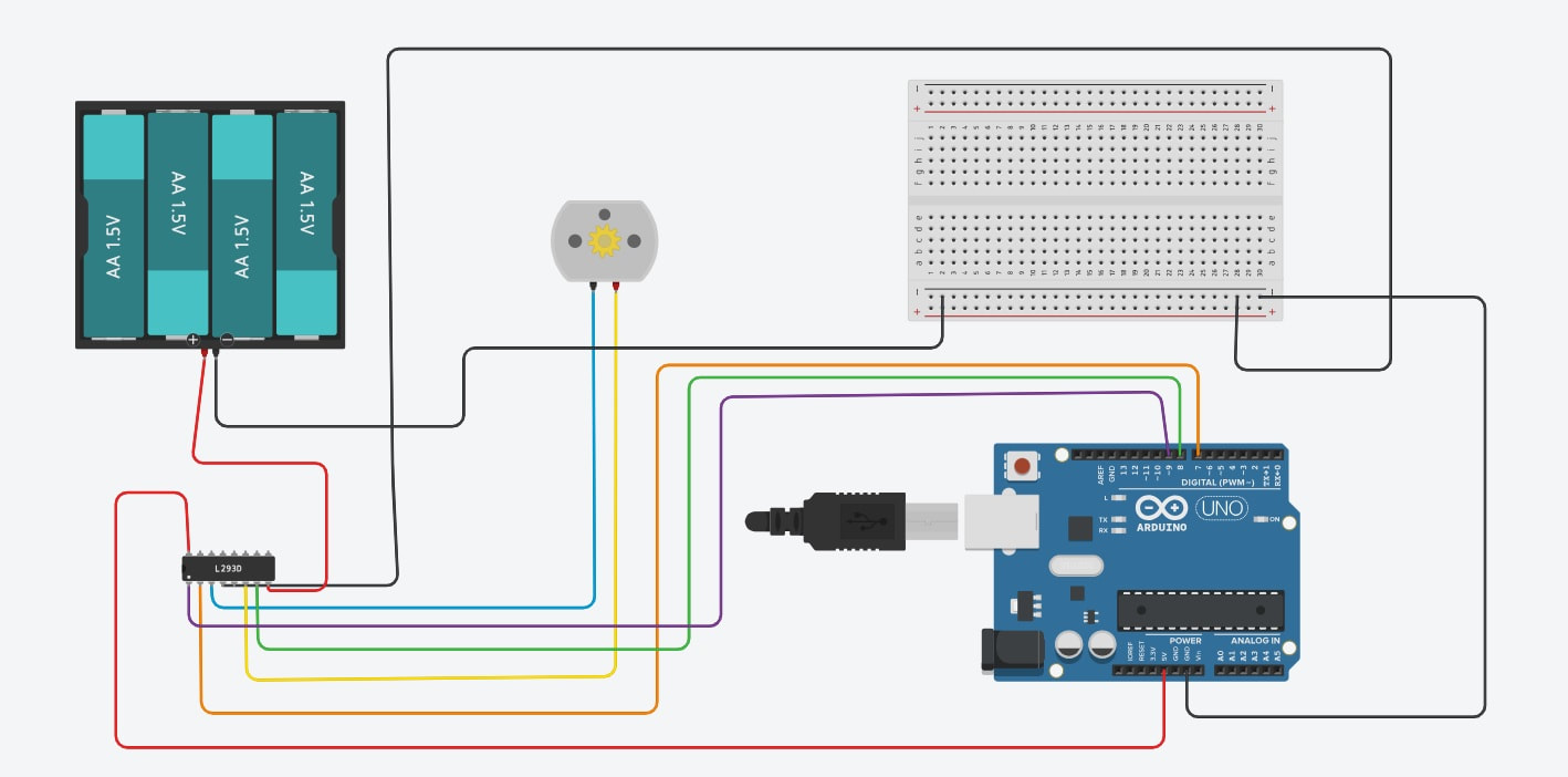
Explanation of the wiring diagram (Figure 2)
The schematic shows the Arduino UNO connected to the L293D driver and a DC motor using an external power supply. The external supply is used only for the motor, while the L293D gets its logic supply from the Arduino.
1. Power connections
The battery holder (2×AA) provides about 3 V and is connected to pin 8 of the L293D (motor supply). The negative battery terminal is connected to the GND of the L293D, and the same GND is connected to the Arduino and the breadboard, so that all devices share a common voltage reference.
2. Logic supply of the L293D
Pin 16 of the L293D is connected to the 5V output of the Arduino. This is the supply the driver uses for its logic, independent of the voltage the motor gets.
3. Driving the motor
The DC motor is connected to the driver outputs – pins 3 and 6. These pins are controlled by the L293D according to the input signals from the Arduino.
4. Control from the Arduino
The Arduino sends control signals to pins 2 and 7 of the L293D. Based on them, the driver sets the direction of the motor. The Enable pin (pin 1) is connected to an Arduino PWM pin (e.g. digital pin 9), which allows speed control with the analogWrite() function.
5. Common ground (GND)
All GND wires (Arduino, batteries, L293D and breadboard) are connected. This is required so that the signals are stable and the driver correctly recognizes the logic levels from the Arduino.
Note
A 6 V supply is a good choice that provides stable operation without the risk of overheating the motor or the L293D driver.
Additional components (optional, but recommended)
The basic schematic does not include extra parts such as capacitors and protection components, but they are often used in real projects to improve stability and extend the life of the motor and electronics. The most important additions are:
- Bypass / decoupling capacitors (100nF – 1µF)
Placed between Vcc and GND on the L293D chip. They reduce supply noise and prevent the Arduino from resetting when the motor load changes suddenly. - Electrolytic capacitor (47µF – 470µF)
Placed close to the motor supply (between +6V and GND). It smooths jerks and voltage drops when the motor suddenly starts or changes direction. - Capacitors directly on the motor (3× 100nF)
One between each motor terminal and the motor case (or GND), plus one directly between the motor terminals.
They reduce electrical noise and brush sparking in DC motors. - Flyback diodes – *not needed with the L293D*
The L293D already has built-in protection diodes for the inductive kickback of the motor, so they are not shown in this schematic.
When can the schematic be used without extra components?
This simplified schematic (without capacitors) usually works well when:
- you use a low-power motor (typical 3–6 V DC toy motors),
- the motor does not change direction often or start under a heavy load,
- the supply is stable and separated from the Arduino, as in this case (separate batteries),
- the project is controlled by a simple Arduino program without timing-sensitive operations.
However, if you notice flickering LEDs, Arduino resets, unstable motor operation, speed changes or noise in other components, adding the capacitors listed above almost always solves the problem.
Example Arduino code for controlling a DC motor with the L298N
The following example shows how an Arduino can control the direction and speed of a DC motor using the L298N driver. The program uses a PWM signal for speed control and digital outputs for the direction.
// Pins connected to the L298N driver
const int IN1 = 7;   // direction control 1
const int IN2 = 8;   // direction control 2
const int ENA = 9;   // PWM output for speed (0–255)

// Keeps the speed in the valid range
int limitSpeed(int value) {
  if (value < 0) return 0;
  if (value > 255) return 255;
  return value;
}

void setup() {
  pinMode(IN1, OUTPUT);
  pinMode(IN2, OUTPUT);
  pinMode(ENA, OUTPUT);
}

// Run the motor forward
void motorForward(int speed) {
  speed = limitSpeed(speed);
  digitalWrite(IN1, HIGH);
  digitalWrite(IN2, LOW);
  analogWrite(ENA, speed);
}

// Run the motor backward
void motorBackward(int speed) {
  speed = limitSpeed(speed);
  digitalWrite(IN1, LOW);
  digitalWrite(IN2, HIGH);
  analogWrite(ENA, speed);
}

// Stop
void motorStop() {
  digitalWrite(IN1, LOW);
  digitalWrite(IN2, LOW);
  analogWrite(ENA, 0);
}

void loop() {
  motorForward(200);   // motor runs forward for 3 seconds
  delay(3000);

  motorBackward(150);  // motor runs backward for 3 seconds
  delay(3000);

  motorStop();         // 2-second pause
  delay(2000);
}
How does this code work?
The L298N driver uses two direction signals (IN1 and IN2) and one PWM signal (ENA) that sets the speed. When the Arduino sets:
IN1 = HIGH,IN2 = LOW— the motor turns forward.IN1 = LOW,IN2 = HIGH— the motor turns backward.IN1 = LOW,IN2 = LOW— the motor is stopped.
The speed is controlled with the analogWrite() function, which sends a PWM signal in the range 0–255 to the ENA pin. The code in loop() only demonstrates a simple movement: 3 seconds forward, 3 backward, then a pause.
Adding a second DC motor (extending the exercise)
In this section we extend the exercise from one DC motor to two independent drive units. The goal is for students to understand how to use the second channel of the H-bridge driver (L293D) to control a second motor — independently or together (e.g. for a simple two-motor vehicle).
What you need (in addition to the one-motor exercise)
- a second DC motor (with similar specifications to the first one)
- extra wires to connect the L293D outputs → second motor
- enough power in the motor supply (if the second motor increases the current, you may need a stronger adapter)
Pin mapping we will use (suggestion for Arduino UNO + L293D module)
To keep the exercise clear, we use the following pin layout:
- Motor A (first motor): IN1 = D7, IN2 = D8, ENA = D9 (PWM)
- Motor B (second motor): IN3 = D5, IN4 = D6, ENB = D10 (PWM)
- Logic: Arduino 5V → Vcc1 (L293D)
- Motor supply: separate adapter / battery → Vcc2 (L293D)
- Common ground: Arduino GND ↔ L293D GND ↔ battery GND
Task for students (clear and measurable)
*Goal of the task:* extend your program and wiring so that you can control two DC motors independently. Implement the following functions:
- Functions for each motor separately:
motorAForward(speed),motorABackward(speed),motorAStop()motorBForward(speed),motorBBackward(speed),motorBStop()
- Functions for combined movements (vehicle):
driveForward(speed)— both motors forwarddriveBackward(speed)— both motors backwardturnLeft(speed)— e.g. motor A stopped or backward, motor B forwardturnRight(speed)— the opposite of the previous one
- In the main loop, write a test sequence: forward, left, right, backward, stop (each action 2–3 s).
- Extra (optional): control the speed of one or both motors with a potentiometer connected to an analog pin.
Success criteria: the student demonstrates all basic functions, the motor does not draw too much current (no crackling), the Arduino does not reset when the motor starts, and all GNDs are connected.
Wiring diagram for two motors
The following diagram (SVG) shows all connections: the control signals, the 5V logic, the motor supply and the outputs for both motors.
Wiring description (step by step)
Following the diagram, make these connections exactly as listed:
- Control signals (Arduino → L293D):
- D9 (PWM) → ENA (enable for motor A)
- D7 → IN1 (motor A direction)
- D8 → IN2 (motor A direction)
- D10 (PWM) → ENB (enable for motor B)
- D5 → IN3 (motor B direction)
- D6 → IN4 (motor B direction)
- Logic: Arduino 5V → Vcc1 (logic pin of the L293D).
- Motor supply: +Vmotor (e.g. 6V) → Vcc2 (L293D). Always connect the battery GND to the L293D GND as well.
- Common ground: connect the Arduino GND to the module GND and to the negative terminal of the battery/PSU.
- Module outputs → motors:
- OUT1 → M_A+
- OUT2 → M_A−
- OUT3 → M_B+
- OUT4 → M_B−
- Capacitors and filtering: it is recommended to place an electrolytic capacitor (e.g. 100–470 µF) between +Vmotor and GND close to the module, and small 0.1 µF ceramic capacitors between Vcc and GND for decoupling. If the motor produces strong spikes or the Arduino resets, add capacitors.
- Check: before switching on, check all connections, the supply polarity and whether the wires are firmly in place. If you use the L293D without an extra heat sink and the motors draw more than ~1–2 A, do not use it without proper cooling.
Final notes for students
- When testing, start with small PWM values (e.g. 120) to observe how the motor behaves.
- If you want to build a vehicle, use the same logic: one wheel = motor A, the other wheel = motor B. By combining directions and speeds you get the required maneuvers.
- Keep a test log: voltage, PWM speed, time and any irregularities (noise, heating, resets).
Explanation of the second DC motor wiring with the L293D and Arduino
The figure shows the correct wiring of two DC motors to the L293D driver and the Arduino UNO. The external 6V supply is used only for the motors, while the Arduino is powered through the USB cable. All ground wires are connected so the system has a common reference point (GND).
1. Power connections
- The 6V battery supply goes to the Vs pin of the L293D chip (pin 8).
- Ground (−) from the batteries is connected to:
- GND of the L293D (pins 4, 5, 12, 13)
- GND of the Arduino UNO
- the GND rail on the breadboard
- 5V from the Arduino goes to Vss (pin 16) and powers the logic side of the L293D chip.
2. Connections for Motor 1
- Motor 1 is connected to pins 3 and 6 of the L293D.
- Pin 2 (IN1) of the L293D goes to an Arduino digital pin – see the wire color in the figure.
- Pin 7 (IN2) of the L293D goes to another Arduino digital pin.
- Pin 1 (Enable 1) is connected to an Arduino PWM pin (e.g. D5 or D6).
3. Connections for Motor 2
- Motor 2 is connected to pins 11 and 14 of the L293D.
- Pin 10 (IN3) goes to an Arduino digital pin.
- Pin 15 (IN4) also goes to a digital pin.
- Pin 9 (Enable 2) is connected to another Arduino PWM pin (e.g. D9).
4. What the Enable pins do
The Enable pins (1 and 9) allow speed control with a PWM signal. When they are connected to Arduino PWM pins, the analogWrite() function can control the speed of both motors independently.
5. Is anything missing?
The schematic is correct, but it is recommended to add three capacitors per motor:
- one between the + and − terminals of the motor (≈ 100 nF ceramic)
- two capacitors from the motor terminals to the motor case
They reduce the interference (EMI) that DC motors create because of their brushes. The system can work without them, especially at lower speeds and loads, but for more stable operation and to prevent Arduino resets they are recommended.
Check your knowledge
Open the quiz
Quiz: DC motor
1. Why is a DC motor not connected directly to an Arduino pin?
2. What does an H-bridge (e.g. L293D or L298N) allow?
3. How is the motor speed changed?
4. What must the Arduino and the motor supply share?