
Measuring an unknown resistor using Arduino and Ohm's law
Excercise Measuring un unknown resistor on arduino
Objective
In this lesson you will learn to measure an unknown resistor using a voltage divider and Arduino.
Task description:
This task uses an Arduino Uno to measure an unknown resistance (Rx) using a simple voltage divider and applying Ohm's Law. The system consists of a known resistor (Rp) and an unknown resistor (Rx) connected in series between the power supply (5V) and ground (GND). The Arduino measures the voltage at the node between these two resistors using analog pin A0.
Goal:
Measure the value of the unknown resistor using the analog input of the Arduino and calculate the current in the circuit using Ohm's law.
Video lesson: Measuring an Unknown Resistor with Ohm’s Law & Arduino UNO
Understanding Ohm’s Law
Ohm’s Law is one of the most fundamental principles in electronics. It defines the relationship between voltage (U), current (I), and resistance (R) in an electrical circuit.
The Formula
U = R ⋅ IIn simple terms, voltage is equal to the product of current and resistance.
□ What Does This Mean?
When electric current flows through a component (like a resistor), it faces some opposition called resistance. To overcome that resistance and keep the current flowing, a certain amount of voltage is needed — like pushing water through a narrow pipe.
For example, if you have a resistor of 100 ohms and a current of 0.1 A, the voltage across the resistor will be:
U = 100 ⋅ 0.1 = 10 VRearranging the Formula
Ohm’s Law can be rearranged to calculate any of the three quantities:
- To find current (I):
- To find resistance (R):
- To find voltage (U):
I = U / RR = U / IU = R ⋅ IWhy Is Ohm’s Law Important?
Ohm’s Law helps engineers and makers to:
- Predict how a circuit will behave
- Choose the right resistor for a component like an LED
- Avoid damaging electronics with too much current
Whether you’re designing a simple LED circuit or working on complex electronics, Ohm’s Law is a tool you’ll use all the time.
In the picture, the resistors are connected in series and then the voltage of 5V is distributed to the resistors. For example, if the voltage on a known resistor is 3V, it means that up to 5V, 2V remains, so we conclude that U_A0=2V.
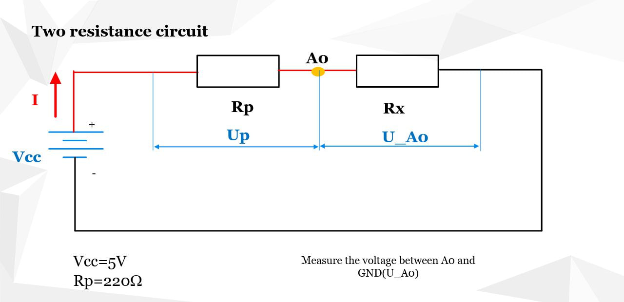
Measuring an Unknown Resistor Using Ohm’s Law and Arduino
In the figure above, you can see a simple voltage divider circuit made of two resistors connected in series:
- Rp – a known resistor (reference resistor)
- Rx – the unknown resistor we want to measure
The Arduino’s analog input pin A0 is connected to the junction point between the two resistors.
This pin reads the voltage drop across the unknown resistor Rx (i.e., the voltage between A0 and GND).
How It Works
The circuit is powered by Vcc (5V) from the Arduino board. Since the two resistors are in series, the same current (I) flows through both of them.
According to Ohm's Law and the rules for resistors in series:
I = const, Rtotal = Rp + RxUsing Ohm's Law:
- The total voltage is:
- The voltage across the unknown resistor (read on A0) is:
- Solving for the current:
- Substituting that expression for current into the formula for Rx:
Vcc = I ⋅ (Rp + Rx)UA0 = I ⋅ Rx ⇒ Rx = UA0 / II = (Vcc − UA0) / RpRx = UA0 ⋅ Rp / (Vcc − UA0)
This final equation allows us to calculate the value of the unknown resistor Rx by measuring the voltage at A0.
□ Notes
-
The analog input pin
A0reads a value from 0 to 1023, corresponding to 0V to 5V (if powered from USB). -
To convert the analog reading into a voltage:
UA0 = analogRead(A0) ⋅ Vcc / 1023
This method is a practical demonstration of Ohm’s Law and the concept of voltage dividers, which are widely used in electronics to measure or scale voltages.
The wires diagram is:
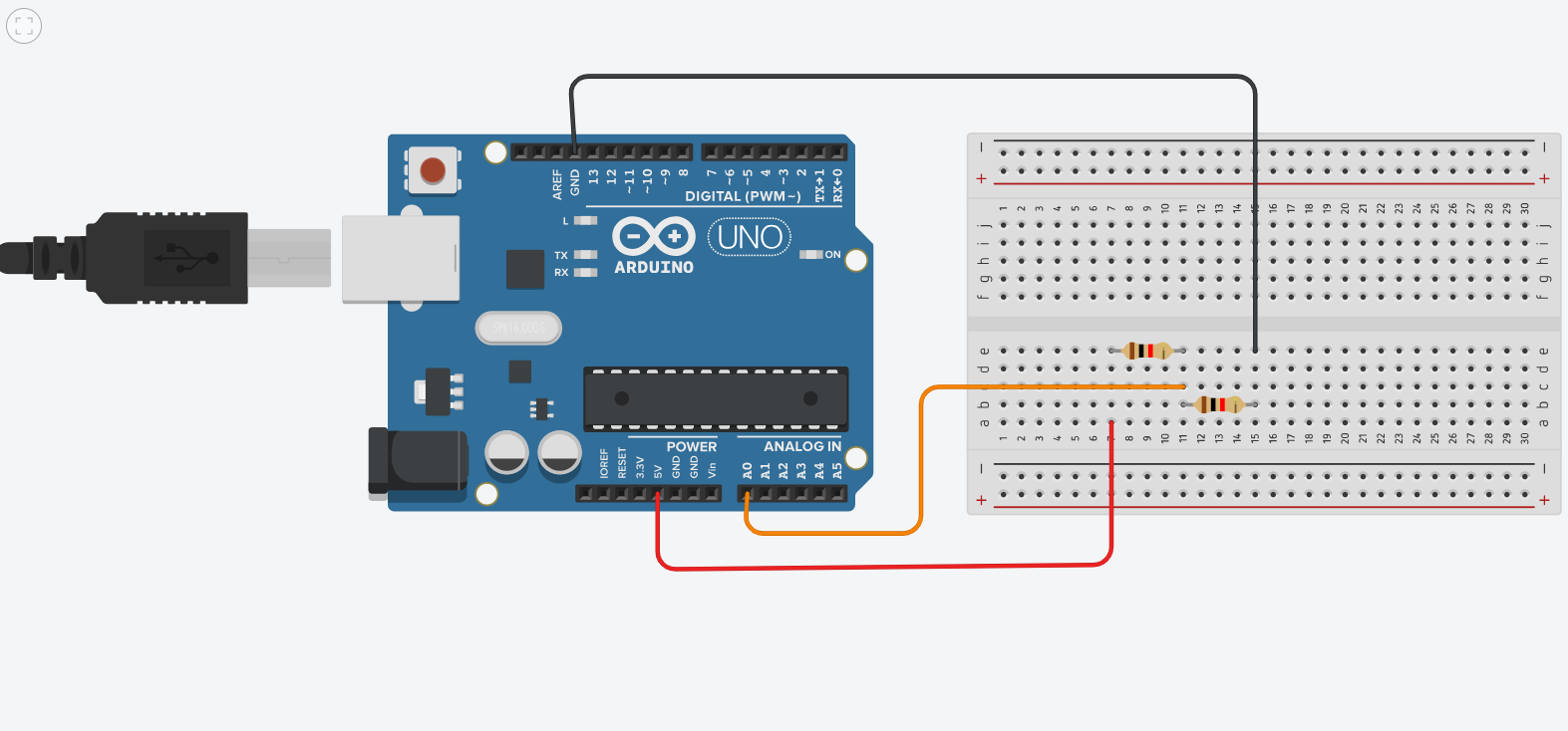
Arduino IDE-code
// Arduino sketch for measuring an unknown resistor Rx using a voltage divider and Ohm's law
constintpin_A0 = A0; // Analog pin A0 is used to read the voltage between known and unknown resistors
floatU_A0; // Voltage at A0
floatanalogValue; // Raw analog value read from A0 (0–1023)
floatRp = 220; // Known resistor value in ohms (Ω)
floatRx; // Calculated value of the unknown resistor
constfloatVcc = 5.0; // Supply voltage (usually 5V on Arduino Uno)
floatI; // Calculated current in amperes
voidsetup()
{
Serial.begin(115200); // Start serial communication at 115200 baud for monitoring results
voidloop()
{
analogValue = analogRead(pin_A0);
// Skip calculation if analog value is 1023 to avoid division by zero
if (analogValue >= 1023)// Skip calculation if analog value is 1023 to avoid division by zero
{
delay(2000); // Wait before next reading
return; // Skip the rest of the loop
// Convert analog value to actual voltage (0–5V)
U_A0 = analogValue * Vcc / 1023.0;
// Calculate unknown resistance Rx using voltage divider formula:
// Rx = U_A0 * Rp / (Vcc - U_A0)
// where:
// - U_A0 is the voltage across Rx
// - Vcc - U_A0 is the voltage across Rp
// - Rp is known resistor
Rx = U_A0 * Rp / (Vcc - U_A0);
// Calculate current using Ohm’s law: I = (Vcc - U_A0) / Rp
// This is the current through the voltage divider
I = (Vcc - U_A0) / Rp;
// Output voltage at A0
Serial.print("U_A0= ");
Serial.print(U_A0);
Serial.println(" V");
// Output current in milliamps
Serial.print("I= ");
Serial.print(1000.0 * I, 2); // Convert to mA and print with 2 decimal places
Serial.println(" mA");
// Output calculated unknown resistance
Serial.print("Rx= ");
Serial.print(Rx);
Serial.println(" ohm");
delay(2000); // Wait 2 seconds before next reading
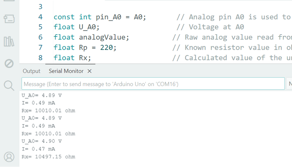
Note on the Voltage Reading Formula for A0
The original formula
U_A0 = analogRead(A0) × Vcc / 1023
is correct. However, some sources divide by 1024 to account for the fact that readings range from 0 to 1023 (i.e., 1024 distinct levels).
The difference is small but can matter in high-precision measurements.
Precision Limitations
• Known resistor tolerance: Common resistors often have a ±5 % tolerance, which can introduce an error of several ohms.
• Arduino ADC accuracy: The 10-bit ADC typically has an uncertainty of ±2 LSB (least significant bits),
which can further affect the final result by a few ohms.
How to Physically Connect the Components to Arduino
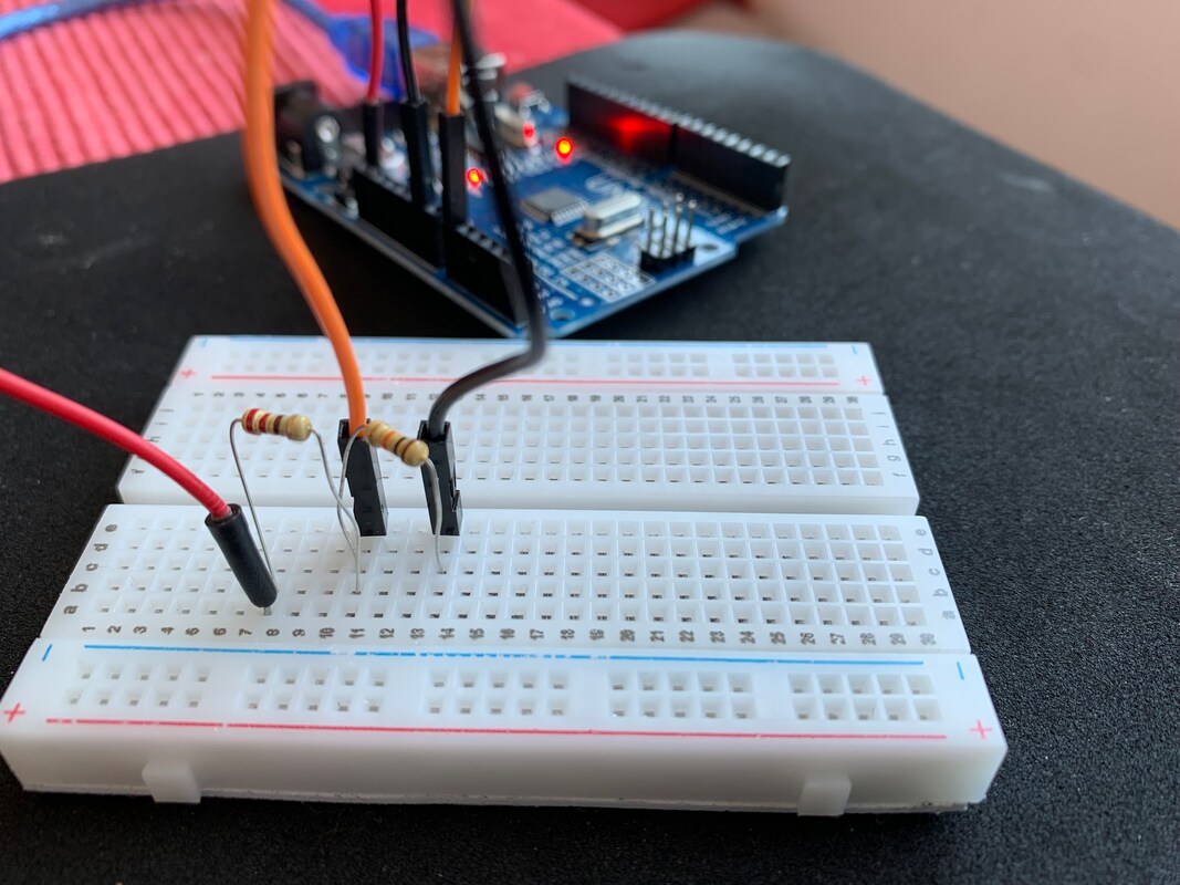
To perform the unknown resistor measurement experiment using Arduino, you need to build a simple voltage divider circuit. Here's how to properly connect the components on a breadboard:
Required Components
- 1 × Arduino UNO board
- 1 × Known resistor (Rp) — e.g., 220Ω or 1kΩ
- 1 × Unknown resistor (Rx) — any resistor you want to measure
- Jumper wires
- 1 × Breadboard
Wiring Instructions
Follow these steps to create the correct electrical connections:
- Connect the Reference Resistor (Rp):
- Connect one leg of the known resistor to the 5V pin on the Arduino.
- Connect the other leg of this resistor to a point on the breadboard where it will be joined with the unknown resistor.
- Connect the Unknown Resistor (Rx):
- One end of the unknown resistor should connect to the same row on the breadboard as the second leg of the reference resistor (they form a series connection).
- The other end of the unknown resistor connects to GND on the Arduino.
- Connect the Analog Input (A0):
- Use a jumper wire to connect the junction point between Rp and Rx (where they meet) to pin A0 on the Arduino.
- This point measures the voltage drop across the unknown resistor.
- Power and Ground:
- Ensure the Arduino is powered through USB or external supply.
- The 5V and GND pins must be used consistently to power the voltage divider circuit.
Troubleshooting & FAQs
Here are some common issues you might encounter and how to resolve them:
- No readings? → Check for a missing or loose ground (GND) connection.
- Always reading maximum value (1023)? → Likely cause: Reference and unknown resistors are wired in reverse, or A0 is directly connected to 5V.
- Unstable or noisy readings? → Possible issues include a floating ground, bad breadboard contacts, or loose jumper wires.
Next Steps & Extensions
Once you’ve successfully measured an unknown resistor, consider trying the following extensions:
- Use the same voltage divider concept to measure analog sensors like the LM35 temperature sensor.
- Improve accuracy by calibrating your setup with a reference resistor of precisely known tolerance (e.g., 1% metal film resistor).
- Visualize your data:
- Send data via serial to Processing and generate live graphs.
- Or display the results directly on a small OLED screen using I2C.
| Previous |< Arduino - Temperature sensor |
Next Arduino-Ultrasonic Sensor >| |