
Light level display (LDR sensor)
A Light Level Display using an LDR (Light Dependent Resistor) is a simple electronic system that measures ambient light intensity and provides a visual representation of it. The LDR sensor changes its resistance based on the amount of light it receives:
- In bright light, the resistance decreases.
- In darkness, the resistance increases.
This change is converted into a voltage and read by an Arduino analog pin. The measured value is then used to control a display, such as a graphical shape on screen (via Processing), or the brightness of an LED (via PWM). This system is often used in automatic lighting, ambient light sensing, and educational projects.
Exercise 2: Using Light sensor – Basic
Let's do an exercise with RGB LED.
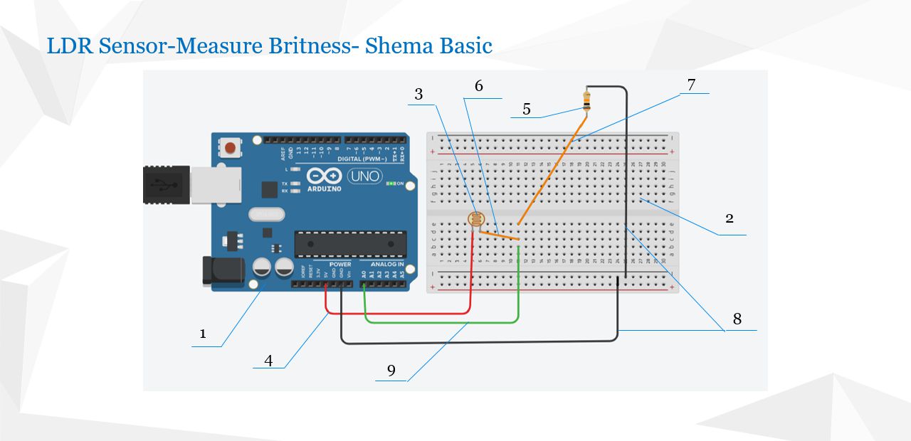
What we need from the equipment is (see Figure 1):
- Arduino Uno board (1)
- The breadboard (2)
- Light sensor (3)
- One resistor of 10 kΩ (5)
- Wires (4, 6, 7, 8, 9)
In this exercise we will measure the level of light in the environment.
We need to use a light sensor, more commonly known as an LDR sensor. This is a photoresistor, which means it changes its resistance when the level of light in the environment changes.
The scheme showing how to connect all the necessary components is presented in Figure 1.
It is very important to keep in mind that you should not connect the Arduino board to your PC while all components aren't connected properly.
You must place a resistor between the 5V pin and the photoresistor because it has a current limit of approximately 1–5 mA. If you exceed this limit, the photoresistor might be damaged.
What happens if you exceed the current limit:
- The LDR heats up, which can:
- Permanently change its resistance (causing incorrect readings in future measurements).
- Melt or burn the material inside the sensor.
- Shorten its lifespan or cause it to stop working completely.
To protect the photoresistor, we will use a permanent resistor connected in series with it.
Video lesson
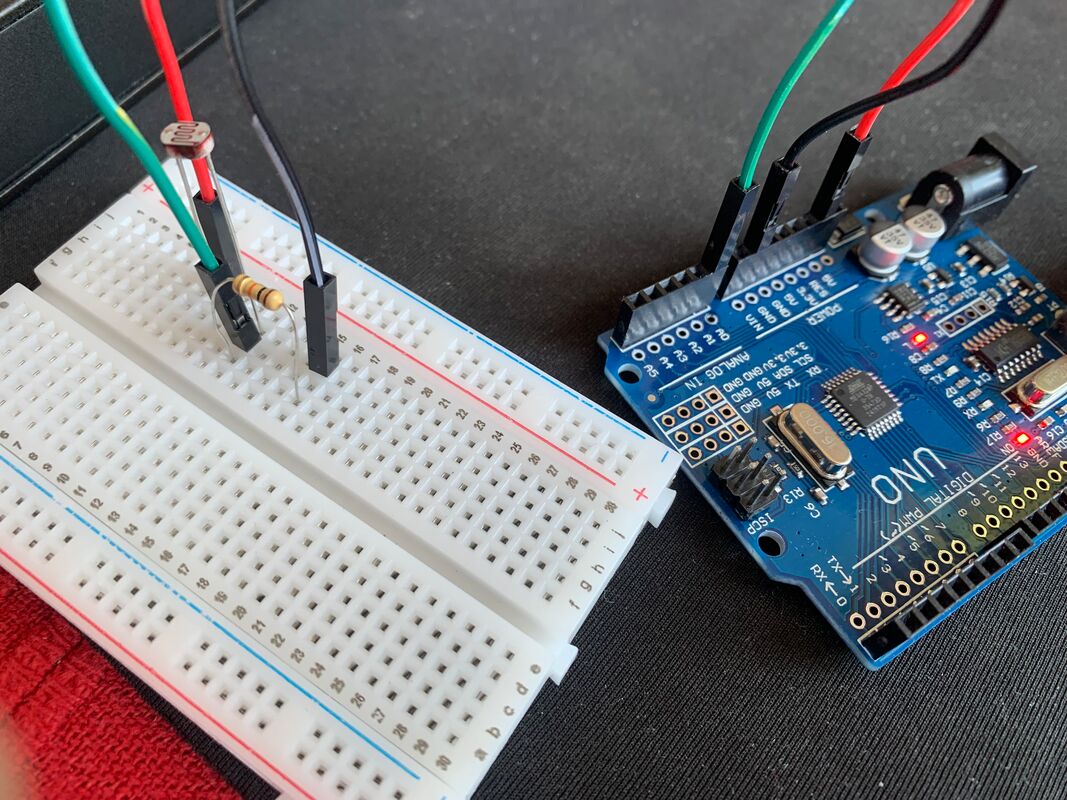
Connection scheme
Connection Scheme
Take a red wire(5) and connect one end to the 5V (VCC) pin on your Arduino. Plug the other end into a row on your breadboard(2).
Insert one leg of the photoresistor LDR(3) into the same row (same voltage) as the red wire. Then place the other leg of the LDR into a new row.
Take a 10kΩ resistor(5) and connect one leg to the same row as the second leg of the LDR. Insert the second leg of the resistor into another row.
Now take a black wire(8) and connect one end to that last row (from the resistor) and the other end to the GND pin on your Arduino.
To read the voltage at the junction between the LDR and the resistor, insert a wire from that middle row (where LDR and resistor are connected together) into the A0 analog input on the Arduino.
Make sure all connections are secure. Once everything is properly connected, you can plug your Arduino into your PC using a USB cable.
constintldrPin = A0;     // Analog input pin connected to the voltage divider between LDR and resistorconstintledPin = 9;      // PWM output pin connected to LED (not used in this code, but declared)voidsetup() {
  // This code runs once when the Arduino is powered on or resetSerial.begin(115200);     // Initialize serial communication at 115200 baud ratepinMode(ldrPin, INPUT);   // Set the LDR pin as an input (optional, analogRead sets it automatically)
}

voidloop() {
  // This code runs continuously in a loopintldrValue = analogRead(ldrPin); // Read the analog value from the LDR (range: 0 to 1023)// Map the LDR value to a brightness value from 255 (dark) to 0 (bright)intbritness = map(ldrValue, 0, 1023, 255, 0);

  // Print the mapped brightness value to the Serial Monitor with label "L:"Serial.print("L:");
  Serial.println(britness);

  delay(100); // Wait for 100 milliseconds before the next reading
}
Explanation of the Arduino Code – Reading Light Level with LDR Sensor
This Arduino program is designed to read the light level from an LDR (Light Dependent Resistor) and send the data to the computer via the Serial Monitor. It helps visualize how light intensity changes over time, which can later be used for various projects, such as controlling LED brightness or triggering actions based on lighting conditions.
How the Circuit Works
- The LDR and a fixed resistor (e.g., 10 kΩ) form a voltage divider.
- One end is connected to 5V, the other to GND, and the middle point is connected to the A0 analog pin on the Arduino.
- As light increases, the resistance of the LDR decreases, changing the voltage at A0.
What the Code Does
const int ldrPin = A0;  // LDR signal pin (connected to the voltage divider)
const int ledPin = 9;   // LED output pin (declared but not used in this example)
ldrPin is assigned to analog pin A0 to read the voltage based on light.
ledPin is declared for future use but is not used in this particular code.
void setup() {
  Serial.begin(115200);   // Start communication with the PC
  pinMode(ldrPin, INPUT); // Set LDR pin as input (not strictly needed)
}
The setup() function runs once and initializes serial communication with the computer at a high speed (115200 baud).
It also sets the pin connected to the LDR as an input.
void loop() {
  int ldrValue = analogRead(ldrPin); // Read analog value (0–1023)
  int britness = map(ldrValue, 0, 1023, 255, 0); // Convert it to brightness (inverted)

  Serial.print("L:");
  Serial.println(britness); // Send the result to the Serial Monitor

  delay(100); // Short pause before repeating
}
The loop() function runs continuously:
– It reads the light level from the LDR.
– It maps the value so that darker = higher brightness (255 means dark, 0 means bright).
– It sends the result in the format L:123 to the Serial Monitor.
– The short delay helps smooth the readings and makes them easier to observe.
What You Can Do with This
- Monitor real-time changes in ambient light.
- Control an LED, motor, or display based on brightness (e.g., turn on lights at night).
- Feed the values into Processing or a graphing tool for real-time visualization.
Processing code
We use Processing to visualize data received from the serial port about the light level in your environment. Read more about how to draw basic shapes in Processing on the following webpage: https://www.svetprogramiranja.com/basics_of_processing_using_java.html .
This application draws a circle and changes its diameter and fill color according to the received data.
importprocessing.serial.*; // Import the Serial library for communication with ArduinoSerialmyPort; // Declare a Serial objectintlightValue = 0; // Variable to store the incoming light sensor valuevoidsetup() {
  size(400, 400); // Set the size of the windowtry {
    if (Serial.list().length > 0) {
      printArray(Serial.list()); // Print the list of available serial ports to the consolemyPort = newSerial(this, Serial.list()[0], 115200); // Open the first available portmyPort.bufferUntil('\n'); // Read serial data until newline character
    } else {
      println("No serial ports available.");
    }
  } catch (Exceptione) {
    println("Error opening serial port: " + e.getMessage());
  }
}

voiddraw() {
  background(0); // Set the background to blackfloatdiameter = map(lightValue, 0, 1023, 300, 50); // Map the light value to circle sizeintbrightness = int(map(lightValue, 0, 1023, 255, 50)); // Map to brightnessfill(brightness, brightness, 255); // Fill with RGB colorellipse(width/2, height/2, diameter, diameter); // Draw the circle
}

voidserialEvent(Serialp) {
  Stringdata = p.readStringUntil('\n'); // Read a line from the serial portif (data != null) {
    data = trim(data); // Remove whitespaceif (data.startsWith("L:")) {
      lightValue = int(data.substring(2)); // Convert string after "L:" to integerprintln("lightValue=" + lightValue);
    }
  }
}
Light level display (LDR sensor) with LED
When the environment is brighter, the resistance of the LDR sensor becomes smaller. This causes a higher voltage to appear across the fixed resistor in the voltage divider, resulting in a higher analog reading on the Arduino.
You can use this reading to programmatically send a proportionally lower signal to a PWM (Pulse Width Modulation) pin, for example pin 9. This pin will act as a voltage source for an LED.
As a result, the LED will receive a lower average voltage and will glow with reduced brightness. This creates a visual effect where the LED gets dimmer as the ambient light increases — mimicking the behavior of an automatic night light.
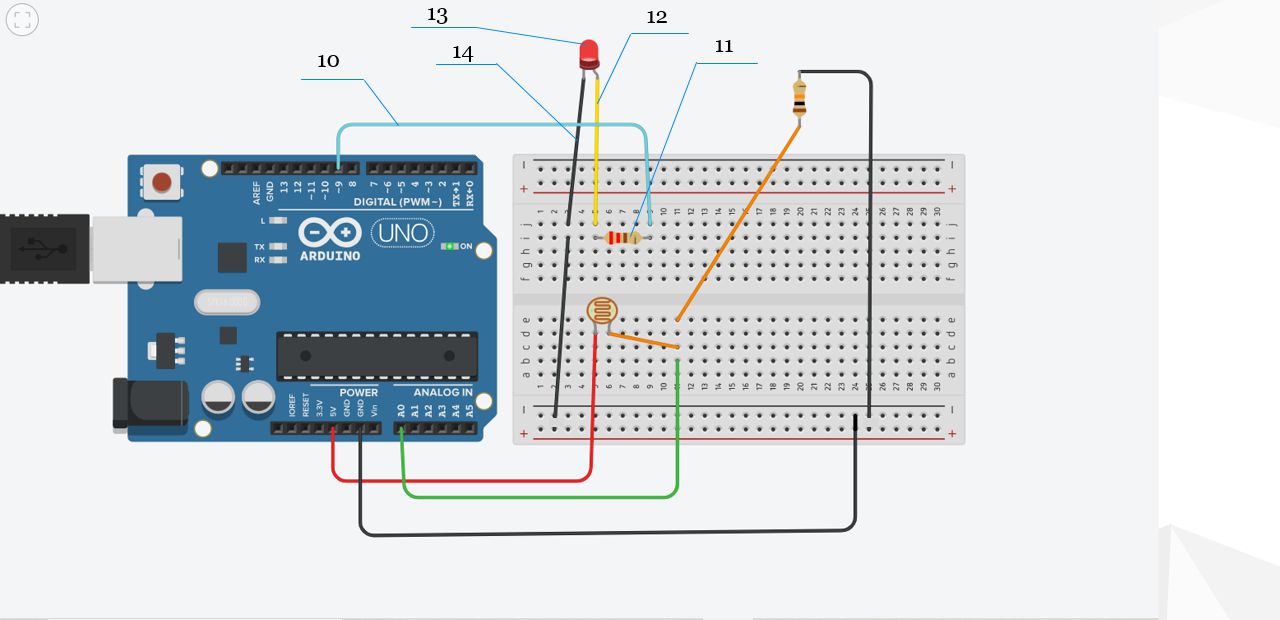
To do this, you can add the following components to the basic exercise:
- LED(13 on figure 4)
- Resistor(11) – 220 Ω
- Wires(10,12,14)
Let's look at Figure 3, which shows how to add the LED and resistor to the breadboard:
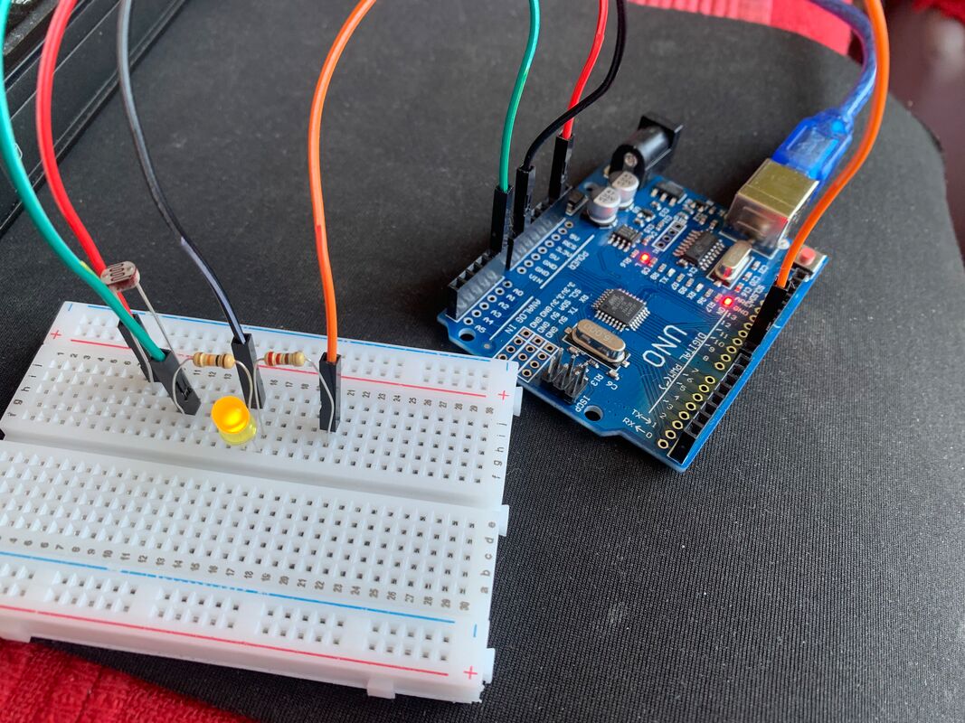
To extend the project with an LED that reflects the light level, you need to connect an LED to one of the PWM-capable pins on the Arduino (e.g., pin 9).
Connect the anode (longer leg) of the LED(13) to pin 9 through a 220Ω resistor(11). The cathode (shorter leg) of the LED should be connected to GND.
Why is the 220Ω resistor necessary?
- LEDs are sensitive components and can be damaged if too much current flows through them.
- The resistor limits the current to a safe level (typically around 10–20mA) to prevent the LED from burning out.
- Without a resistor, the LED could draw too much current from the Arduino pin, which could damage both the LED and the microcontroller.
This setup allows the Arduino to control the brightness of the LED using analogWrite() on pin 9, where higher light levels result in lower brightness and vice versa.
constintldrPin = A0;     // Analog input pin connected to the voltage divider (LDR + resistor)constintledPin = 9;      // PWM output pin connected to LEDvoidsetup() {
  // This code runs once when the Arduino is powered on or resetSerial.begin(115200);       // Start serial communication at 115200 baudpinMode(ledPin, OUTPUT);// Set LED pin as outputpinMode(ldrPin, INPUT);     // Set LDR pin as input (optional, analogRead does this automatically)
}

voidloop() {
  // This code runs repeatedly in a loopintldrValue = analogRead(ldrPin); // Read analog value from LDR (0 = dark, 1023 = bright)// Map the LDR reading to a brightness level (inverted: darker room = higher brightness)intbritness = map(ldrValue, 0, 1023, 255, 0);

  // Write the calculated brightness to the LED using PWManalogWrite(ledPin, britness);// Send the brightness value to the Serial Monitor for observationSerial.print("L:");
  Serial.println(britness);

  delay(100); // Wait for 100 milliseconds before the next reading
}
In the extended version of the code, an LED is added and controlled using a PWM (Pulse Width Modulation) signal from pin 9 of the Arduino board.
The LED is physically connected in series with a 220Ω resistor to limit the current flowing through it.
Why is the resistor necessary?
Without the resistor, the LED might receive too much current directly from the 5V source, which could result in:
- Overheating the LED.
- Permanent damage to the LED or even the Arduino pin.
- Shortened lifespan or total failure of the LED.
The resistor ensures that the current stays within a safe range for the LED, typically around 15–20 mA. A value of 220Ω is commonly used for standard red, green, or blue LEDs.
In the program, we calculate the brightness level from the light sensor (LDR), and send that value to the LED using the analogWrite() function on pin ledPin. As a result:
- In bright environments (low resistance of the LDR), the LED glows dimly.
- In darker environments (high resistance of the LDR), the LED glows brighter.
| Previous |< Introduction to Arduino |
Next Arduino - Temperature sensor >| |