
Controlling a water pump with ESP32 — the basis of a smart garden
To build a smart garden, we need to control a water pump that can be switched on and off by a microcontroller when needed. Controlling the pump is the basis of an automated watering system.
A water pump usually runs on 12 V DC, although depending on the model it can also run on 6–12 V. It is very important to stress that the pump must never be powered directly from the microcontroller (in our case the ESP32), because:
- the ESP32 uses 3.3 V logic,
- the GPIO pins cannot provide enough current to run the pump,
- there is a risk of permanently damaging the microcontroller.
That is why an external power supply is used (e.g. a 12 V battery or adapter), and a relay is used to switch the pump on and off safely.
Relay — how it works
A relay is an electromechanical switch that allows a low-voltage microcontroller to control a device with higher voltage and current.
Inside, a relay contains:
- a coil (electromagnet),
- a moving armature,
- three contacts: COM, NO and NC.
When current flows through the coil, it creates a magnetic field that pulls the armature and changes the position of the contacts. This closes or opens the pump circuit.
The advantage of a relay is that the control circuit (ESP32 – 3.3 V) and the power circuit (pump – 6 to 12 V) stay separated.
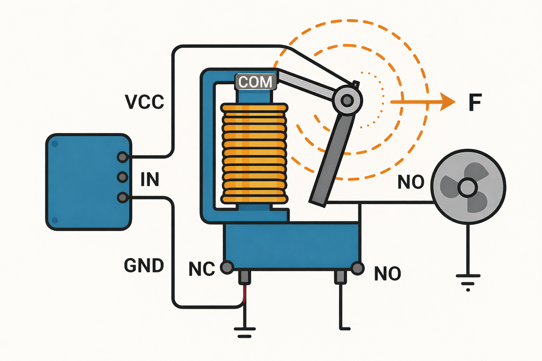
Explanation of the relay diagram
The figure shows how a relay works, with the control part and the power part of the circuit clearly marked.
Control part (left)
- VCC – relay module supply (usually 5 V)
- GND – ground (shared with the ESP32)
- IN – control signal from a GPIO pin
When the ESP32 sends a logic signal to the IN pin, current flows through the relay coil. The coil creates a magnetic field that pulls the moving armature.
Power part (right)
- COM – common (moving) contact
- NO – normally open contact
- NC – normally closed contact
The diagram uses the NO contact, which means the load (pump or motor) is off while the relay is not activated.
When the relay is activated:
- the armature moves,
- COM connects to the NO contact,
- the circuit closes,
- the pump gets power and starts running.
Which wiring variant is shown?
This diagram shows Variant 1 — switching the positive (+) supply line.
In this variant:
- the positive supply terminal goes to COM,
- NO goes to the positive terminal of the pump,
- the negative terminal of the pump goes directly to the negative supply terminal.
This is the most common wiring in practice because it is clear, simple and considered the safer solution in DC systems.
⚠ Safety note (AC mains voltage)
If the relay is used to control devices on mains voltage (220–230 V AC), always switch the live wire (L), not the neutral (N).
Switching the live wire ensures that the device is really without voltage when it is off, which reduces the risk of electric shock during servicing or when touching the installation.
Working with mains voltage requires special care, good insulation and following electrical safety standards. Students should not work with mains voltage.
Relay module terminals
The relay module we use has six terminals: three for control (low voltage) and three for the pump supply (higher voltage).
Control terminals
- VCC
- GND
- IN
The connection to the ESP32 is as follows:
VCC (relay) → 5V (ESP32 VIN)
GND (relay) → GND (ESP32)
IN (relay)  → GPIO 23
The ESP32 GPIO pins work at 3.3 V, which is enough to drive the input of the relay module. It is very important that the relay GND and the ESP32 GND are connected.
Pump supply contacts
On the other side of the relay there are three terminals:
- COM – common (moving) contact
- NO – normally open contact
- NC – normally closed contact
COM is the middle contact which, depending on the state of the relay, connects to NO or NC.
Variant 1 — switching the positive line (recommended)
In this variant the positive (+) supply line is switched.
+12V → COM
NO   → + pump
- pump → -12V
While the relay is not activated:
- COM and NO are not connected,
- the circuit is open,
- the pump does not run.
When the signal from GPIO23 activates the relay:
- the electromagnet pulls the armature,
- COM and NO connect,
- the pump gets voltage and starts running.
The NC contact stays unconnected in this variant.
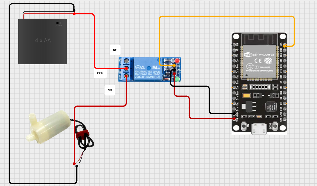
ESP32 controlling a 5V pump through a relay
In this exercise the ESP32 controls a small 5V DC pump using a relay module. The pump is not connected directly to the ESP32 because the GPIO pins work at 3.3V and cannot provide enough current for the motor. The relay is used as an electronic switch that allows the pump to be switched on and off safely.
Relay module pin labels (Cirkit Designer)
Control part (low voltage)
- VCC – relay module supply (5V)
- GND – ground (must be shared with the ESP32)
- IN – control signal from the ESP32 (e.g. GPIO23)
Switching part (power – pump)
- COM (Common) – receives the +5V pump supply
- NO (Normally Open) – connected to the + of the pump
- NC (Normally Closed) – not used in this exercise
Wiring variant (Variant 1 – switching the plus line)
In this diagram the relay switches the positive supply line of the pump. When the relay is activated, COM and NO connect and +5V reaches the pump.
How it works
When the ESP32 sends a HIGH signal to the IN pin:
- the relay (the coil inside the module) is activated
- COM and NO are mechanically connected
- the pump gets +5V and starts running
When the signal is LOW:
- the relay is inactive
- COM and NO are not connected
- the pump is off
Text diagram
ESP32 GPIO ----> IN (relay)
ESP32 GND  ----> GND (relay)
5V --------> VCC (relay)

+5V --------> COM
NO ---------> + pump
- pump -----> GND
Important notes
- The pump must have a suitable 5V supply.
- The GND of the pump supply and the GND of the ESP32 must be shared (common ground).
- The relay module already contains a transistor and a protection diode, so it can be connected directly to the ESP32.
- The NC pin is used only if we want the pump to run while the relay is inactive.
Variant 2 — switching the negative line
In this variant the negative (−) supply line is switched.
+12V → + pump
- pump → COM
NO → -12V
Electrically, both variants are correct. The only difference is whether the positive or the negative line is switched.
In practice switching the positive line is used more often, because it is considered clearer and safer.
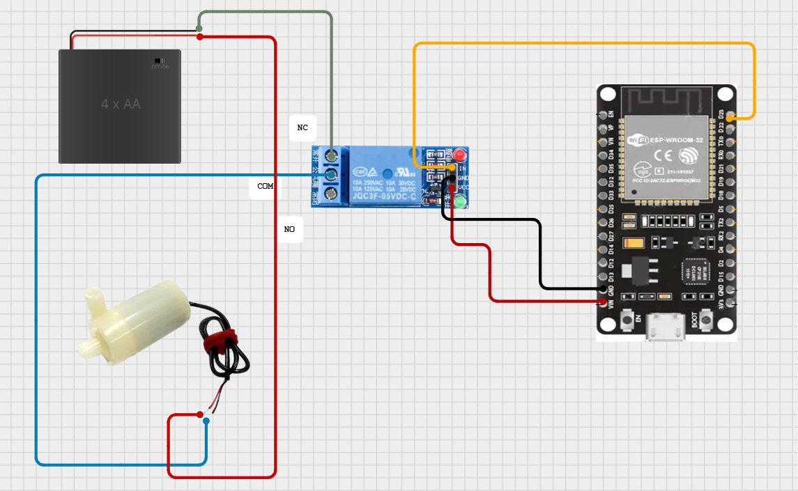
The figure below shows the wiring in which the relay switches the negative (−) supply line of the pump. The positive supply terminal (+6V) goes directly to the pump, and the negative terminal goes to the COM contact of the relay.
When the ESP32 sends a HIGH signal to the IN pin of the relay module, the relay coil is activated and the COM and NO contacts connect. This connects the negative supply line to the pump, the circuit closes and the pump starts running.
When the signal from the ESP32 is LOW, COM and NO are not connected, the circuit is open and the pump is off.
It is important to note that the ESP32 does not power the pump directly. The pump uses a separate 6V supply, and the relay acts as an electrical switch that allows safe control of a device with higher voltage and current.
Although switching the negative line is electrically completely correct, in practice the positive line is switched more often because that solution is clearer and more intuitive for most users.
Important notes and recommendations
- Never apply 6V (or the higher pump voltage) directly to the ESP32.
- The pump must have a separate supply (6V in this exercise).
- Always connect the ESP32 GND and the relay module GND (common GND).
- Most projects use the NO (Normally Open) contact of the relay.
- Since the pump is a DC motor, it is recommended to place a protection diode in parallel with the pump (flyback diode) to reduce voltage spikes when it switches off.
- The relay module already contains a transistor and a protection diode for the coil, which makes it a safer and simpler solution for beginners.
The relay allows the ESP32 to control the pump safely with a small control signal (3.3V), while the pump is powered by a separate source.
This configuration is often used in automatic watering systems, smart gardens and IoT projects.
Controlling the pump from the Serial Monitor
In this example the ESP32 controls the relay module and the pump through the Serial Monitor. Sending the character '1' switches the pump on, and '0' switches it off.
const int relayPin = 23;
const bool RELAY_ON  = HIGH;   // for a relay that switches on with LOW (LOW-trigger), swap HIGH and LOW
const bool RELAY_OFF = LOW;

void setup() {
  Serial.begin(115200);
  pinMode(relayPin, OUTPUT);
  digitalWrite(relayPin, RELAY_OFF); // pump off
  Serial.println("System ready. Send 1 for ON, 0 for OFF.");
}

void loop() {
  if (Serial.available()) {
    char command = Serial.read();
    if (command == '1') {
      digitalWrite(relayPin, RELAY_ON);  // switch the pump on
      Serial.println("Pump ON");
    }
    else if (command == '0') {
      digitalWrite(relayPin, RELAY_OFF); // switch the pump off
      Serial.println("Pump OFF");
    }
  }
}
Code explanation:
1. Pin 23 of the ESP32 is defined as an output and connected to the IN pin of the relay module.
2. The constants RELAY_ON and RELAY_OFF set the relay logic (HIGH activates a HIGH-trigger module; for a LOW-trigger module swap HIGH and LOW).
3. The relay starts switched off, so the pump does not run at startup.
4. The Serial.available() function checks whether a new character has arrived from the Serial Monitor.
5. If the user sends '1', the relay is activated and the pump switches on.
6. If the user sends '0', the relay is switched off and the pump stops.
7. A common GND between the ESP32 and the relay module is important when the pump has a separate supply.
Signal flow in the ESP32 + relay + pump system
The following diagram shows how the ESP32 signal controls the pump through the relay:
ESP32 GPIO (digital pin 23)
          |
          v
       IN pin
   of the relay module
          |
          v
      COM contact
          |
          v
      NO contact
          |
          v
       6V pump
          |
          v
      Common GND
Signal flow:
1. The ESP32 sends a HIGH or LOW signal to the IN pin of the relay module.
2. The module activates or deactivates the relay coil according to the HIGH/LOW logic.
3. When the COM and NO contacts are connected, the pump circuit is complete and the pump runs.
4. When the contacts are separated, the pump is off.
5. A common GND is required so that the ESP32, the relay and the pump share the same voltage reference.
6. This is a simple, safe and reliable way for the ESP32 to control a low-voltage DC pump.
Controlling the pump from Processing
This section shows how the ESP32 pump can be controlled from the computer with a Processing program over the serial port. We use the same ESP32 serial code that reads '1' and '0' to switch the pump on or off.
Processing code:
import processing.serial.*;

Serial myPort;

void setup() {
  size(200, 200);
  // Check which port the ESP32 uses:
  println(Serial.list());
  myPort = new Serial(this, Serial.list()[0], 115200);
}

void draw() {
  background(220);
  textAlign(CENTER, CENTER);
  textSize(16);
  text("Press '1' for pump ON\nPress '0' for pump OFF", width/2, height/2);
}

void keyPressed() {
  if (key == '1') {
    myPort.write('1'); // switch the pump on
    println("Sent: 1 (pump ON)");
  } else if (key == '0') {
    myPort.write('0'); // switch the pump off
    println("Sent: 0 (pump OFF)");
  }
}
Code explanation:
1. We import the processing.serial.* library to use the serial port.
2. Serial.list() prints the available ports, and we choose the port the ESP32 is on.
3. In draw() we simply show a text interface with instructions.
4. In keyPressed() we send the character '1' or '0' to the serial port when the matching key is pressed.
5. The ESP32 receives the character and controls the relay according to the previous code.
Notes and recommendations:
- The simplest format is sending a single character ('1' or '0').
- You can also send strings such as "ON\n" or "OFF\n", but then the ESP32 code must use
Serial.readStringUntil('\n'). - Check that the baud rate is the same in Processing and on the ESP32 (115200 here).
- The ESP32 must be properly connected to the computer (USB cable) for the serial signal to work.
- In Processing,
Serial.list()[0]is the first port – check the console output to choose the right port.
This kind of communication allows simple control of the pump from the computer and can easily be extended with GUI controls, sensor inputs or automated functions.
Check your knowledge
Open the quiz
Quiz: pump and relay
1. Why is the pump not powered directly from an ESP32 pin?
2. What is a relay?
3. Which relay contact is the pump connected to so that it is off while the relay is idle?
4. How is the pump switched on from the computer in the lesson?