
Arduino: LED, button and traffic light
After the first program from the lesson Introduction to Arduino we build real little circuits on a breadboard. We will learn how to connect an LED correctly, how the Arduino reads a button and how three LEDs become a traffic light – including a traffic light with a pedestrian button.
What we need
- Arduino Uno (or a clone) and a USB cable
- a breadboard and jumper wires
- three LEDs: red, yellow and green
- three 220 Ω resistors (red-red-brown)
- one four-pin push button
The LED and the resistor
An LED lets current flow in one direction only. The long leg is the anode (+) and goes towards the Arduino pin, the short leg is the cathode (−) and goes to GND. If you put it in the wrong way round, nothing breaks – it just does not light up.
An LED is never connected without a resistor. Without it, too much current would flow and both the LED and the pin could burn out. A 220 Ω resistor limits the current to about 13 mA: (5 V − 2 V) / 220 Ω ≈ 0.013 A. The resistor can be on either side of the LED.
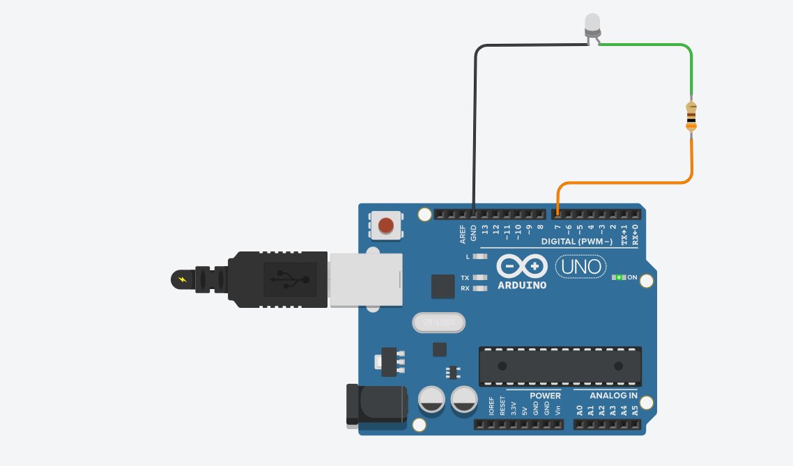
Program 1: LED on pin 7
// Arduino – LED on pin 7 blinks
const int LED = 7;              // LED (long leg) through a 220 ohm resistor to pin 7

void setup() {
  pinMode(LED, OUTPUT);         // pin 7 is an output
}

void loop() {
  digitalWrite(LED, HIGH);      // on: the pin is at 5 V
  delay(1000);                  // wait 1 second
  digitalWrite(LED, LOW);       // off: the pin is at 0 V
  delay(1000);
}
pinMode(LED, OUTPUT) in setup() says that the pin is an output. In loop(), HIGH (5 V, LED on) and LOW (0 V, LED off) take turns, with a 1000 ms pause in between.
The button and INPUT_PULLUP
A button has four legs that are connected in two pairs inside. Place it across the middle of the breadboard, then connect one leg to pin 2 and the diagonal leg to GND.
A pin that is not connected anywhere "floats" and reads random values. That is why we use pinMode(BUTTON, INPUT_PULLUP): a resistor inside the Arduino is turned on and keeps the pin HIGH. When we press the button, the pin is connected to GND and reads LOW.
| Button | digitalRead() reads | In the Serial Monitor |
|---|---|---|
| released | HIGH | 1 |
| pressed | LOW | 0 |
INPUT_PULLUP the logic is "upside down" – a pressed button gives LOW. This is normal and the most common way to connect a button.Program 2: the LED is on while we hold the button
// Arduino – the LED is on while we hold the button
const int LED = 7;
const int BUTTON = 2;           // button between pin 2 and GND

void setup() {
  pinMode(LED, OUTPUT);
  pinMode(BUTTON, INPUT_PULLUP);   // the internal resistor keeps the pin HIGH
  Serial.begin(9600);
}

void loop() {
  int state = digitalRead(BUTTON);
  Serial.println(state);          // 1 = released, 0 = pressed
  if (state == LOW) {
    digitalWrite(LED, HIGH);
  } else {
    digitalWrite(LED, LOW);
  }
  delay(50);
}
Open the Serial Monitor (9600) and press the button – you will see 1 change to 0.
Program 3: the button as a switch
// Arduino – each press turns the LED on or off (like a light switch)
const int LED = 7;
const int BUTTON = 2;

bool isOn = false;
int previous = HIGH;           // button state in the previous pass through loop()

void setup() {
  pinMode(LED, OUTPUT);
  pinMode(BUTTON, INPUT_PULLUP);
}

void loop() {
  int now = digitalRead(BUTTON);
  if (previous == HIGH && now == LOW) {   // the moment the button is pressed
    isOn = !isOn;                   // toggle the state
    digitalWrite(LED, isOn ? HIGH : LOW);
    delay(30);                              // wait for the contact to stop "bouncing"
  }
  previous = now;
}
Here we do not check whether the button is pressed, but the moment it gets pressed: last time it was HIGH and now it is LOW. Without this, the LED would flicker as long as we hold the button, because loop() repeats thousands of times per second.
The short 30 ms pause solves contact "bounce": when pressed, the metal contacts inside the button touch and separate several times very quickly, so the Arduino would see one press as several.
Traffic light
Connect three LEDs, each with its own resistor, to pins 12, 7 and 4. The cathodes (short legs) go to the common GND line at the edge of the breadboard.
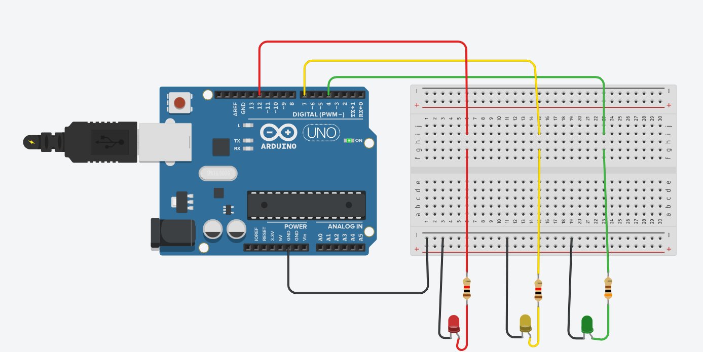
| Light | Pin | Duration in the program |
|---|---|---|
| red | 12 | 5 s |
| red + yellow | 12 and 7 | 2 s |
| green | 4 | 5 s, then blinks 3 times |
| yellow | 7 | 2 s |
// Arduino – traffic light: red, red + yellow, green, blinking green, yellow
const int RED = 12;
const int YELLOW = 7;
const int GREEN = 4;

// helper function: turns on exactly the lights we choose
void lights(int c, int z, int g) {
  digitalWrite(RED, c);
  digitalWrite(YELLOW, z);
  digitalWrite(GREEN, g);
}

void setup() {
  pinMode(RED, OUTPUT);
  pinMode(YELLOW, OUTPUT);
  pinMode(GREEN, OUTPUT);
}

void loop() {
  lights(HIGH, LOW, LOW);       // red
  delay(5000);
  lights(HIGH, HIGH, LOW);      // red + yellow: get ready
  delay(2000);
  lights(LOW, LOW, HIGH);       // green
  delay(5000);
  for (int i = 0; i < 3; i++) { // green blinks 3 times
    lights(LOW, LOW, LOW);
    delay(500);
    lights(LOW, LOW, HIGH);
    delay(500);
  }
  lights(LOW, HIGH, LOW);       // yellow
  delay(2000);
}
The lights(c, z, g) function makes the program shorter: instead of three digitalWrite lines we write one. Helper functions like this make programs easier to read.
Pedestrian traffic light
Add a button on pin 2 (the other leg to GND). Cars have green until a pedestrian presses the button; then the light changes to red and back to green.
// Arduino – traffic light with a pedestrian button
// Cars have green until a pedestrian presses the button.
const int RED = 12;
const int YELLOW = 7;
const int GREEN = 4;
const int BUTTON = 2;

void lights(int c, int z, int g) {
  digitalWrite(RED, c);
  digitalWrite(YELLOW, z);
  digitalWrite(GREEN, g);
}

void setup() {
  pinMode(RED, OUTPUT);
  pinMode(YELLOW, OUTPUT);
  pinMode(GREEN, OUTPUT);
  pinMode(BUTTON, INPUT_PULLUP);
  lights(LOW, LOW, HIGH);       // at the start: green for cars
}

void loop() {
  if (digitalRead(BUTTON) == LOW) {   // a pedestrian pressed the button
    delay(1000);                      // cars do not stop instantly
    lights(LOW, HIGH, LOW);           // yellow
    delay(2000);
    lights(HIGH, LOW, LOW);           // red: pedestrians cross
    delay(6000);
    lights(HIGH, HIGH, LOW);          // red + yellow
    delay(2000);
    lights(LOW, LOW, HIGH);           // green again
    delay(5000);                      // at least 5 s of green before the next press
  }
}
While delay() is running, the Arduino does nothing else – it does not even read the button. That is why a press during the red light has no effect. In the third task below you will see how millis() solves this.
Common mistakes
- The LED does not light up: it is the wrong way round or not in the same breadboard row as the resistor and the wire.
- The button "works by itself":
INPUT_PULLUPis missing, so the pin floats. - The button never works: both wires are on legs that are already connected – turn the button by 90°.
- All LEDs are dim:
pinMode(..., OUTPUT)is missing for those pins.
Practice tasks
Try to solve each task yourself first, then open the solution.
- Make a "running light": three LEDs (pins 4, 7 and 12) light up one at a time, forward and back.
- Count button presses and print them in the Serial Monitor. After the fifth press, the LED on pin 7 blinks 3 times and counting starts again.
- Add a night mode to the traffic light: a button press switches it to blinking yellow, and the next press returns normal operation. The button must react immediately, even while a light is on.
Solution 1: running light
// Task – "running light": three LEDs light up in turn, forward and back
const int PINS[3] = { 4, 7, 12 };

void setup() {
  for (int i = 0; i < 3; i++) {
    pinMode(PINS[i], OUTPUT);
  }
}

void lightOnly(int k) {
  for (int i = 0; i < 3; i++) {
    digitalWrite(PINS[i], i == k ? HIGH : LOW);
  }
}

void loop() {
  for (int k = 0; k < 3; k++) {     // forward
    lightOnly(k);
    delay(200);
  }
  for (int k = 1; k >= 0; k--) {    // back (without repeating the end LED)
    lightOnly(k);
    delay(200);
  }
}
Solution 2: press counter
// Task – press counter: after 5 presses the LED blinks 3 times
const int LED = 7;
const int BUTTON = 2;
int count = 0;
int previous = HIGH;

void setup() {
  pinMode(LED, OUTPUT);
  pinMode(BUTTON, INPUT_PULLUP);
  Serial.begin(9600);
}

void loop() {
  int now = digitalRead(BUTTON);
  if (previous == HIGH && now == LOW) {
    count++;
    Serial.print("Presses: ");
    Serial.println(count);
    if (count == 5) {
      for (int i = 0; i < 3; i++) {
        digitalWrite(LED, HIGH);
        delay(200);
        digitalWrite(LED, LOW);
        delay(200);
      }
      count = 0;                   // start counting again
    }
    delay(30);
  }
  previous = now;
}
Solution 3: night mode with millis()
// Task – traffic light with night mode: the button switches to blinking yellow and back
const int RED = 12;
const int YELLOW = 7;
const int GREEN = 4;
const int BUTTON = 2;
bool night = false;

void lights(int c, int z, int g) {
  digitalWrite(RED, c);
  digitalWrite(YELLOW, z);
  digitalWrite(GREEN, g);
}

// waits the given time, but keeps checking the button
void waitFor(unsigned long ms) {
  unsigned long start = millis();
  while (millis() - start < ms) {
    if (digitalRead(BUTTON) == LOW) {
      night = !night;
      while (digitalRead(BUTTON) == LOW) {
        delay(10);                // wait until the button is released
      }
      return;                     // switch to the new mode immediately
    }
  }
}

void setup() {
  pinMode(RED, OUTPUT);
  pinMode(YELLOW, OUTPUT);
  pinMode(GREEN, OUTPUT);
  pinMode(BUTTON, INPUT_PULLUP);
}

void loop() {
  if (night) {
    lights(LOW, HIGH, LOW);
    waitFor(500);
    if (!night) return;
    lights(LOW, LOW, LOW);
    waitFor(500);
  } else {
    lights(HIGH, LOW, LOW);
    waitFor(5000);
    if (night) return;
    lights(HIGH, HIGH, LOW);
    waitFor(2000);
    if (night) return;
    lights(LOW, LOW, HIGH);
    waitFor(5000);
    if (night) return;
    lights(LOW, HIGH, LOW);
    waitFor(2000);
  }
}
Check your knowledge
Open the quiz
Quiz: LED, button and traffic light
1. Which LED leg goes towards the Arduino pin?
2. Why is a 220 Ω resistor connected with the LED?
3. What does digitalRead() return when a button with INPUT_PULLUP is pressed?
4. Why does the button switch react only to the change HIGH → LOW?