
ESP32: light sensor and LED ring (WS2812)
In the lesson on measuring light the ESP32 turned on one LED when it got dark. Now we use an LED ring with 12 RGB LEDs (WS2812, also known as NeoPixel) instead. Each LED on the ring can have its own color, and all of them are controlled through a single pin. We build a night light that turns on more LEDs the darker it is.
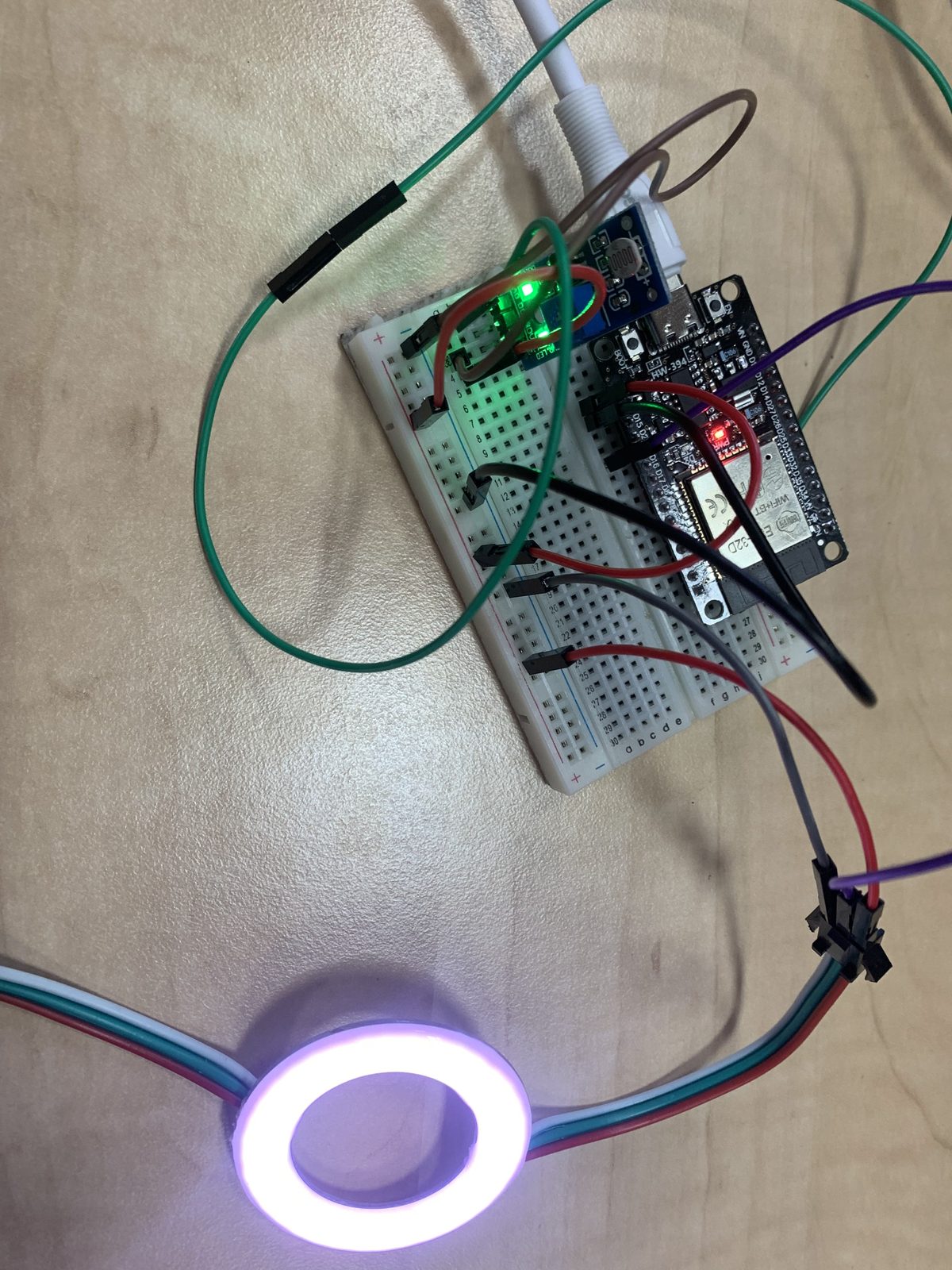
How the LED ring works
- Each LED contains three tiny LEDs (red, green and blue) and a small chip that remembers the color.
- The ESP32 sends a stream of data to the DIN (IN) input. The first LED takes its color and passes the rest on to the next one – like a message passed down a line.
- A color is given by three numbers from 0 to 255:
Color(red, green, blue). For exampleColor(255, 0, 0)is red andColor(255, 255, 255)is white. - At full brightness one LED uses up to 60 mA – 12 LEDs almost 0.75 A. That is why we reduce the brightness with
setBrightness().
Wiring
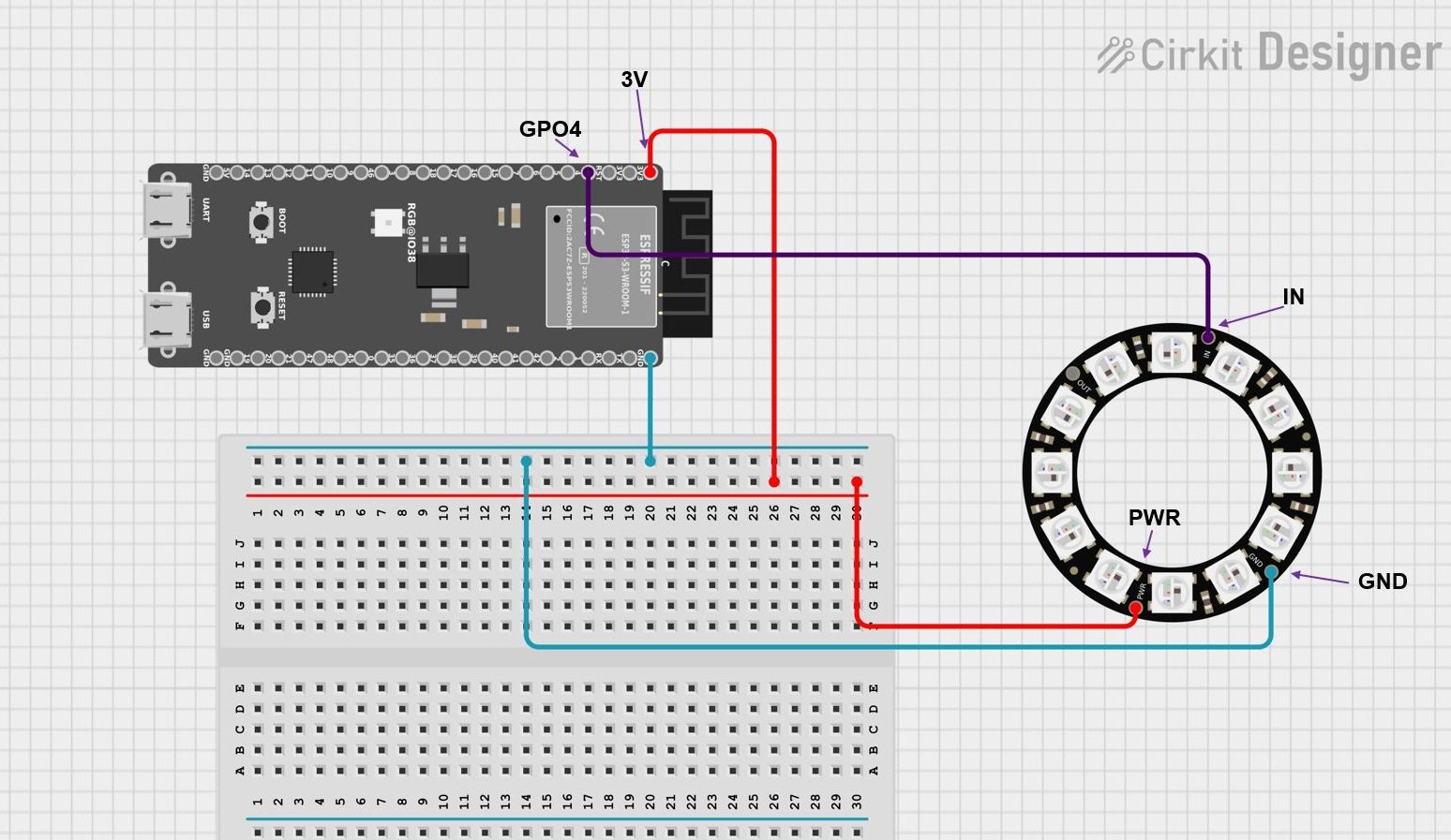
| Part | Pin | ESP32 |
|---|---|---|
| LED ring | PWR (5V/VCC) | 3V3 (for 12 LEDs at low brightness) or 5V (VIN) |
| LED ring | GND | GND |
| LED ring | IN (DIN) | GPIO4 |
| LDR module | VCC | 3V3 |
| LDR module | GND | GND |
| LDR module | AO (analog output) | GPIO34 |
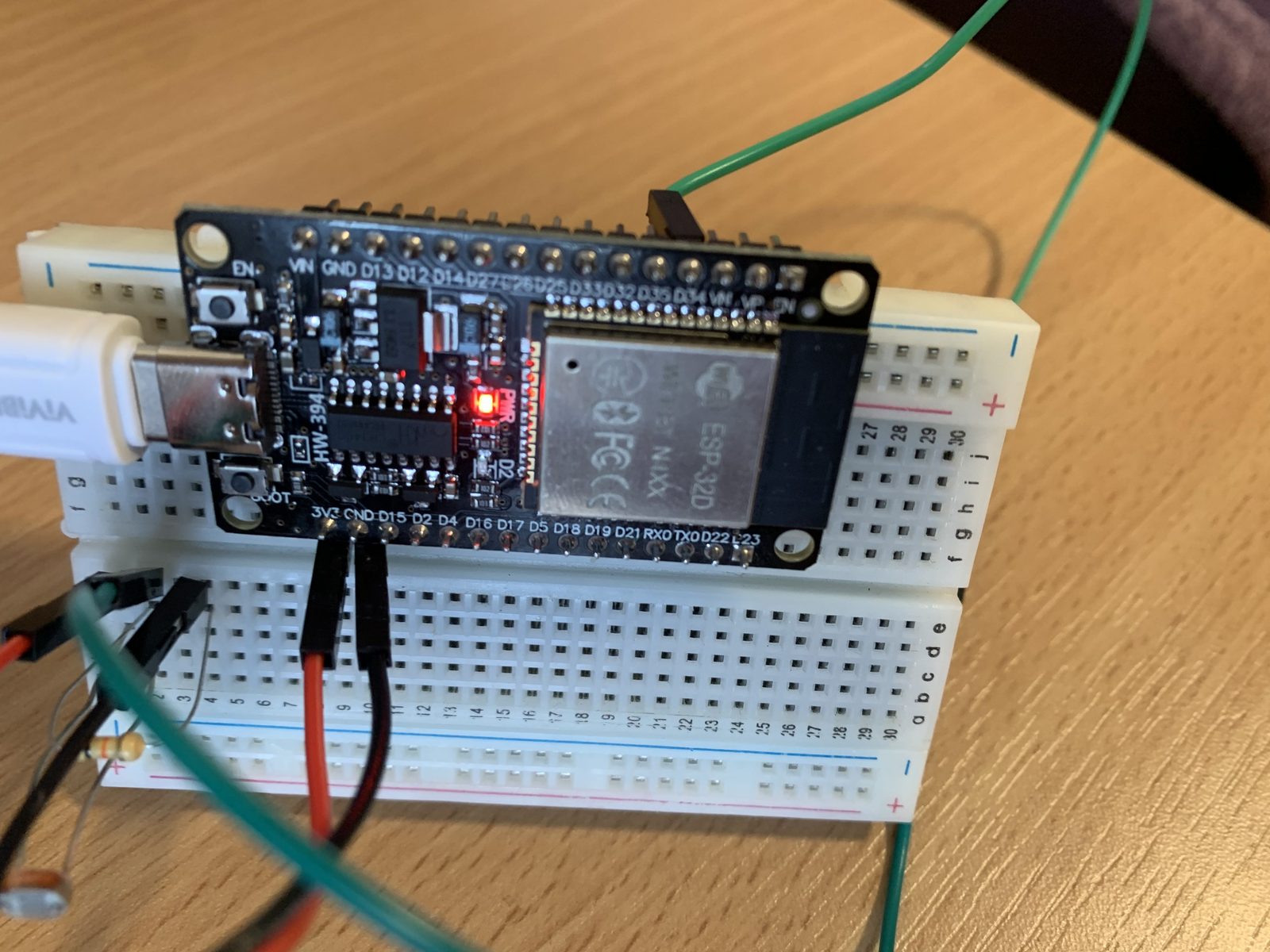
Step 1: ring test
In the Arduino IDE install the Adafruit NeoPixel library (Sketch → Include Library → Manage Libraries). The first program only checks that the ring works – the LEDs light up one by one in three colors:
// ESP32 – LED ring test (WS2812 / NeoPixel)
// Library: Adafruit NeoPixel (Library Manager)
#include <Adafruit_NeoPixel.h>

const int RING_PIN = 4;       // ring DIN (IN) on GPIO4
const int NUM_LEDS = 12;        // number of LEDs on the ring (12, 16 or 24)

Adafruit_NeoPixel ring(NUM_LEDS, RING_PIN, NEO_GRB + NEO_KHZ800);

void setup() {
  ring.begin();
  ring.setBrightness(40);     // 0–255; low brightness saves current (and your eyes)
}

void loop() {
  // LEDs light up one by one – red, green, blue
  uint32_t colors[3] = { ring.Color(255, 0, 0), ring.Color(0, 255, 0), ring.Color(0, 0, 255) };
  for (int b = 0; b < 3; b++) {
    for (int i = 0; i < NUM_LEDS; i++) {
      ring.setPixelColor(i, colors[b]);
      ring.show();            // only show() sends the colors to the ring
      delay(60);
    }
  }
  ring.clear();
  ring.show();
  delay(300);
}
Important: setPixelColor() only stores the color in the ESP32's memory. The ring changes only when we call show().
Step 2: night light
Now we read the LDR sensor and from the number returned by analogRead() we calculate how many LEDs should be on. On most LDR modules the value grows when it gets darker; if yours works the other way round, swap the LIGHT and DARK values.
// ESP32 – night light: the darker it is, the more LEDs are on
#include <Adafruit_NeoPixel.h>

const int LDR_PIN = 34;         // AO output of the LDR module (ADC1)
const int RING_PIN = 4;
const int NUM_LEDS = 12;

// calibration: read the values in the Serial Monitor and enter your own
const int LIGHT = 800;         // value when the room is lit
const int DARK   = 3500;        // value when the sensor is covered by a hand

Adafruit_NeoPixel ring(NUM_LEDS, RING_PIN, NEO_GRB + NEO_KHZ800);

void setup() {
  Serial.begin(115200);
  ring.begin();
  ring.setBrightness(60);
}

void loop() {
  int ldr = analogRead(LDR_PIN);              // most modules: bigger number = darker
  int litCount = map(ldr, LIGHT, DARK, 0, NUM_LEDS);
  litCount = constrain(litCount, 0, NUM_LEDS);

  for (int i = 0; i < NUM_LEDS; i++) {
    if (i < litCount) {
      ring.setPixelColor(i, ring.Color(255, 160, 40));   // warm white
    } else {
      ring.setPixelColor(i, 0);                            // off
    }
  }
  ring.show();

  Serial.print("LDR: ");
  Serial.print(ldr);
  Serial.print("  LEDs on: ");
  Serial.println(litCount);
  delay(100);
}
Calibration
- Run the program and open the Serial Monitor (115200).
- Write down the LDR value with the room light on – that is
LIGHT. - Cover the sensor with your hand and write down the value – that is
DARK. - Enter these numbers in the program and upload it again.
map() can give a number below 0 or above 12 (if it is brighter than during calibration), which is why constrain() follows it.
Practice tasks
- Change the color of the night light to blue or green.
- Make the ring flash red when it is completely dark (all LEDs should be on).
- Make the ring "breathe": the brightness slowly changes from 10 to 150 and back.
- Let the color depend on the light: yellow in the light, blue in the dark, and a blend in between.
Solution: color depends on the light
// Task – the color depends on light: blue in the dark, yellow in the light
#include <Adafruit_NeoPixel.h>

const int LDR_PIN = 34;
const int RING_PIN = 4;
const int NUM_LEDS = 12;

Adafruit_NeoPixel ring(NUM_LEDS, RING_PIN, NEO_GRB + NEO_KHZ800);

void setup() {
  ring.begin();
  ring.setBrightness(50);
}

void loop() {
  int ldr = constrain(analogRead(LDR_PIN), 0, 4095);
  int t = map(ldr, 0, 4095, 0, 255);          // 0 = light, 255 = dark
  // mix yellow (255, 200, 0) and blue (0, 0, 255) in proportion to t
  int r = map(t, 0, 255, 255, 0);
  int g = map(t, 0, 255, 200, 0);
  int b = map(t, 0, 255, 0, 255);
  ring.fill(ring.Color(r, g, b));
  ring.show();
  delay(50);
}
Check your knowledge
Open the quiz
Quiz: light sensor and LED ring
1. Through how many signal pins does the ESP32 control all LEDs of the ring?
2. What must be called so the ring shows the new colors after setPixelColor()?
3. Which color does Color(0, 0, 255) give?
4. Why does constrain() follow map()?