
ESP32 and the MPU9250: accelerometer, gyroscope and magnetometer in one module
In the lesson accelerometer and magnetometer we used two separate modules. The MPU9250 module has everything in one: an accelerometer (acceleration and tilt), a gyroscope (rotation speed) and a magnetometer (compass) – nine measured quantities in total, which is why it is called a "9-axis" sensor. Mobile phones, drones and smartwatches have sensors like this.
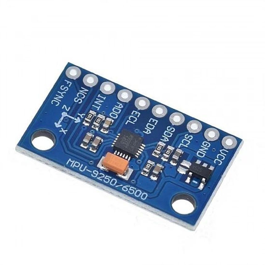
What is in the module
| Sensor | Measures | Unit | Example use |
|---|---|---|---|
| accelerometer (3 axes) | acceleration, including gravity | g (1 g ≈ 9.81 m/s²) | tilt, shaking, step counter |
| gyroscope (3 axes) | rotation speed | °/s (degrees per second) | how far an object has turned, drone stabilization |
| AK8963 magnetometer (3 axes) | magnetic field | µT (microtesla) | compass – direction of north |
| thermometer | chip temperature | °C | measurement correction (not air temperature) |
0x71 or 0x73 means MPU9250, 0x70 means MPU6500.Wiring (I2C)
| MPU9250 | ESP32 | Note |
|---|---|---|
| VCC | 3V3 | the module has a regulator and also runs on 3.3 V |
| GND | GND | |
| SCL | GPIO22 | I2C clock |
| SDA | GPIO21 | I2C data |
| AD0 | not connected (or GND) | address 0x68; on 3V3 the address is 0x69 |
We do not need the other pins (EDA, ECL, INT, NCS, FSYNC). You can connect the module to the same SDA and SCL wires as other I2C modules – each has its own address.
Step 1: I2C scanner and WHO_AM_I
// ESP32 – I2C scanner: does the MPU9250 answer, and which chip is it?
#include <Wire.h>

void setup() {
  Serial.begin(115200);
  Wire.begin(21, 22);           // SDA = GPIO21, SCL = GPIO22
  delay(100);

  for (int address = 1; address < 127; address++) {
    Wire.beginTransmission(address);
    if (Wire.endTransmission() == 0) {
      Serial.print("Found a device at 0x");
      Serial.println(address, HEX);
    }
  }

  // The WHO_AM_I register (0x75) tells which chip is really on the module
  Wire.beginTransmission(0x68);
  Wire.write(0x75);
  Wire.endTransmission(false);
  Wire.requestFrom(0x68, 1);
  int id = Wire.read();
  Serial.print("WHO_AM_I = 0x");
  Serial.println(id, HEX);
  if (id == 0x71 || id == 0x73) {
    Serial.println("MPU9250/MPU9255 – it has a magnetometer too.");
  } else if (id == 0x70) {
    Serial.println("MPU6500 – accelerometer and gyroscope only (no magnetometer).");
  } else {
    Serial.println("Unknown chip – check the wiring.");
  }
}

void loop() {
}
A device is expected at 0x68. At first the magnetometer is not visible – it is inside the same package, but "behind" the main chip. We unlock it in step 3.
Step 2: accelerometer and gyroscope
As with the MPU6050, we wake the sensor by writing 0 to register 0x6B, then read pairs of bytes: acceleration from register 0x3B, temperature from 0x41 and the gyroscope from 0x43.
// ESP32 – MPU9250: accelerometer, gyroscope and temperature (no extra libraries)
#include <Wire.h>

const int MPU = 0x68;           // I2C address (AD0 to GND)

void writeRegister(int device, int reg, int value) {
  Wire.beginTransmission(device);
  Wire.write(reg);
  Wire.write(value);
  Wire.endTransmission();
}

// reads a signed 16-bit number: high byte first, then low byte (big-endian)
int16_t read16(int reg) {
  Wire.beginTransmission(MPU);
  Wire.write(reg);
  Wire.endTransmission(false);
  Wire.requestFrom(MPU, 2);
  int16_t high = Wire.read();
  int16_t low = Wire.read();
  return (int16_t)((high << 8) | low);
}

void setup() {
  Serial.begin(115200);
  Wire.begin(21, 22);
  writeRegister(MPU, 0x6B, 0x00);   // PWR_MGMT_1 = 0: wakes the sensor
  delay(100);
}

void loop() {
  // accelerometer: ±2 g, 16384 units = 1 g
  float ax = read16(0x3B) / 16384.0;
  float ay = read16(0x3D) / 16384.0;
  float az = read16(0x3F) / 16384.0;
  // chip temperature (not air!)
  float temp = read16(0x41) / 333.87 + 21.0;
  // gyroscope: ±250 °/s, 131 units = 1 °/s
  float gx = read16(0x43) / 131.0;
  float gy = read16(0x45) / 131.0;
  float gz = read16(0x47) / 131.0;

  // tilt from the accelerometer (valid while the module is still)
  float tiltForward = atan2(ay, az) * 180.0 / PI;
  float tiltSide = atan2(-ax, sqrt(ay * ay + az * az)) * 180.0 / PI;

  Serial.print("a[g]: ");
  Serial.print(ax, 2); Serial.print(" "); Serial.print(ay, 2); Serial.print(" "); Serial.print(az, 2);
  Serial.print("  w[°/s]: ");
  Serial.print(gx, 1); Serial.print(" "); Serial.print(gy, 1); Serial.print(" "); Serial.print(gz, 1);
  Serial.print("  tilt: ");
  Serial.print(tiltForward, 0); Serial.print(" / "); Serial.print(tiltSide, 0);
  Serial.print("  T: ");
  Serial.println(temp, 1);
  delay(200);
}
| Quantity | Raw number | Divide by | Result |
|---|---|---|---|
| acceleration (±2 g) | −32768 … 32767 | 16384 | g |
| angular speed (±250 °/s) | −32768 … 32767 | 131 | °/s |
| temperature | … | 333.87 (then + 21) | °C |
- When the module lies flat and still, the accelerometer shows about Z = 1 g and the gyroscope about 0 (with a small error – the offset).
- When you turn it, the gyroscope shows how fast it is turning, not its position. The position is found by adding up: angle = speed · time (task 3).
Step 3: magnetometer and compass
Writing 0x02 to register 0x37 turns on bypass: the main chip "lets through" the I2C connection to the AK8963 magnetometer at address 0x0C. Then we switch the magnetometer to continuous measurement.
// ESP32 – MPU9250: AK8963 magnetometer and compass
#include <Wire.h>

const int MPU = 0x68;
const int MAG = 0x0C;           // the AK8963 is "hidden" behind the MPU

void writeRegister(int device, int reg, int value) {
  Wire.beginTransmission(device);
  Wire.write(reg);
  Wire.write(value);
  Wire.endTransmission();
}

int readByte(int device, int reg) {
  Wire.beginTransmission(device);
  Wire.write(reg);
  Wire.endTransmission(false);
  Wire.requestFrom(device, 1);
  return Wire.read();
}

void setup() {
  Serial.begin(115200);
  Wire.begin(21, 22);
  writeRegister(MPU, 0x6B, 0x00);   // wake the MPU
  delay(100);
  writeRegister(MPU, 0x37, 0x02);   // INT_PIN_CFG: BYPASS – AK8963 visible on I2C
  delay(10);
  writeRegister(MAG, 0x0A, 0x00);   // magnetometer: off (before changing mode)
  delay(10);
  writeRegister(MAG, 0x0A, 0x16);   // 16 bits, continuous measurement at 100 Hz
  delay(10);
  Serial.print("AK8963 WIA (should be 0x48): 0x");
  Serial.println(readByte(MAG, 0x00), HEX);
}

void loop() {
  if (readByte(MAG, 0x02) & 0x01) {           // ST1: a new measurement is ready
    Wire.beginTransmission(MAG);
    Wire.write(0x03);                          // HXL – first data byte
    Wire.endTransmission(false);
    Wire.requestFrom(MAG, 7);                  // 6 bytes + ST2 (must be read)
    uint8_t b[7];
    for (int i = 0; i < 7; i++) {
      b[i] = Wire.read();
    }
    // low byte first, high byte second (little-endian) – opposite of the accelerometer
    int16_t mx = (int16_t)(b[1] << 8 | b[0]);
    int16_t my = (int16_t)(b[3] << 8 | b[2]);
    int16_t mz = (int16_t)(b[5] << 8 | b[4]);
    // b[6] is ST2 – now that it is read, the sensor can prepare a new measurement

    // 0.15 µT per unit (16-bit mode)
    float bx = mx * 0.15;
    float by = my * 0.15;
    float bz = mz * 0.15;

    // heading: module flat, chip facing up
    float direction = atan2(by, bx) * 180.0 / PI;
    if (direction < 0) {
      direction += 360;
    }

    Serial.print("B[uT]: ");
    Serial.print(bx, 1); Serial.print(" "); Serial.print(by, 1); Serial.print(" "); Serial.print(bz, 1);
    Serial.print("  heading: ");
    Serial.println(direction, 0);
  }
  delay(100);
}
- The magnetometer byte order is reversed: low byte first, then high byte. That is why the program first reads all 7 bytes into an array and then puts them together.
- After the data, the ST2 register must also be read – only then does the sensor prepare a new measurement.
- The magnetometer axes are not the same as the accelerometer axes (X and Y are swapped and Z is reversed). For a compass on a table this does not matter, but for advanced calculations it must be taken into account.
- Like any compass, this one needs calibration – the procedure is the same as in the lesson accelerometer and magnetometer: turn the module in a circle and remember the smallest and largest X and Y values.
Comparison: MPU9250, two modules and the micro:bit
| MPU9250 | MPU6050 + QMC5883L | micro:bit v2 | |
|---|---|---|---|
| number of modules | 1 | 2 | built in |
| accelerometer | yes | yes | yes |
| gyroscope | yes | yes (MPU6050) | no |
| magnetometer | yes (AK8963, 0x0C) | yes (QMC5883L, 0x0D) | yes |
| I2C addresses | 0x68 and 0x0C | 0x68 and 0x0D | – |
| programming | registers, bypass | registers | ready-made commands |
Practice tasks
- Print "SHAKEN!" when the total acceleration
sqrt(ax² + ay² + az²)goes above 2 g. - Turn on the LED (GPIO2) when the module is tilted forward by more than 30°.
- Calculate how many degrees the module has turned around the Z axis by adding up gyroscope readings (measure the offset at rest first).
- Build a compass with four LEDs (N, E, S, W) – the LED of the direction closest to the module's heading lights up.
Solution: rotation angle from the gyroscope
// Task – rotation angle around the Z axis by adding up gyroscope readings
#include <Wire.h>

const int MPU = 0x68;
float angleZ = 0;                // total angle in degrees
float offsetZ = 0;             // gyroscope error at rest
unsigned long previous = 0;

int16_t read16(int reg) {
  Wire.beginTransmission(MPU);
  Wire.write(reg);
  Wire.endTransmission(false);
  Wire.requestFrom(MPU, 2);
  int16_t high = Wire.read();
  int16_t low = Wire.read();
  return (int16_t)((high << 8) | low);
}

void setup() {
  Serial.begin(115200);
  Wire.begin(21, 22);
  Wire.beginTransmission(MPU);
  Wire.write(0x6B);
  Wire.write(0x00);
  Wire.endTransmission();
  delay(100);
  // calibration: 200 readings while the module is still
  for (int i = 0; i < 200; i++) {
    offsetZ += read16(0x47) / 131.0;
    delay(5);
  }
  offsetZ /= 200;
  previous = millis();
}

void loop() {
  unsigned long now = millis();
  float dt = (now - previous) / 1000.0;       // elapsed time in seconds
  previous = now;
  float speed = read16(0x47) / 131.0 - offsetZ;   // °/s
  angleZ += speed * dt;                         // angle = speed · time
  Serial.print("Angle Z: ");
  Serial.println(angleZ, 1);
  delay(10);
}
Check your knowledge
Open the quiz
Quiz: MPU9250
1. What does a gyroscope measure?
2. Which WHO_AM_I value does an MPU6500 (no magnetometer) return?
3. What must be done to see the AK8963 magnetometer at address 0x0C?
4. How many raw units are 1 g in the ±2 g range?