
ESP32: first program – LED, button and PWM
Just like with the Arduino, the first program on a new board is a blinking LED. On the ESP32 the program looks almost the same, but there are important differences: the pins work at 3.3 V, the analog input is 12-bit (0–4095), and LED brightness is set with the ledc functions. In this lesson we write four short programs: blink, button, a "breathing" LED and a potentiometer.
Setup: ESP32 in the Arduino IDE
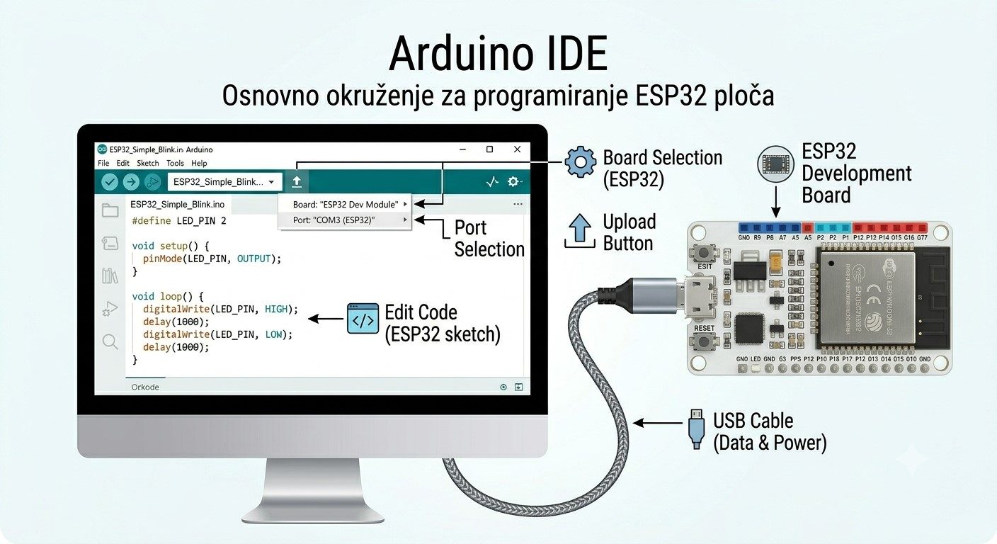
- In the Arduino IDE open Tools → Board → Boards Manager, search for esp32 and install esp32 by Espressif Systems.
- Choose the ESP32 Dev Module board and the port the board is connected to (Tools → Port).
- If no port appears, install the driver for the board's USB chip (CP2102 or CH340) – just like for Arduino clones.
- If uploading stops at "Connecting…", hold the BOOT button on the board until writing starts.
ESP32 board pins
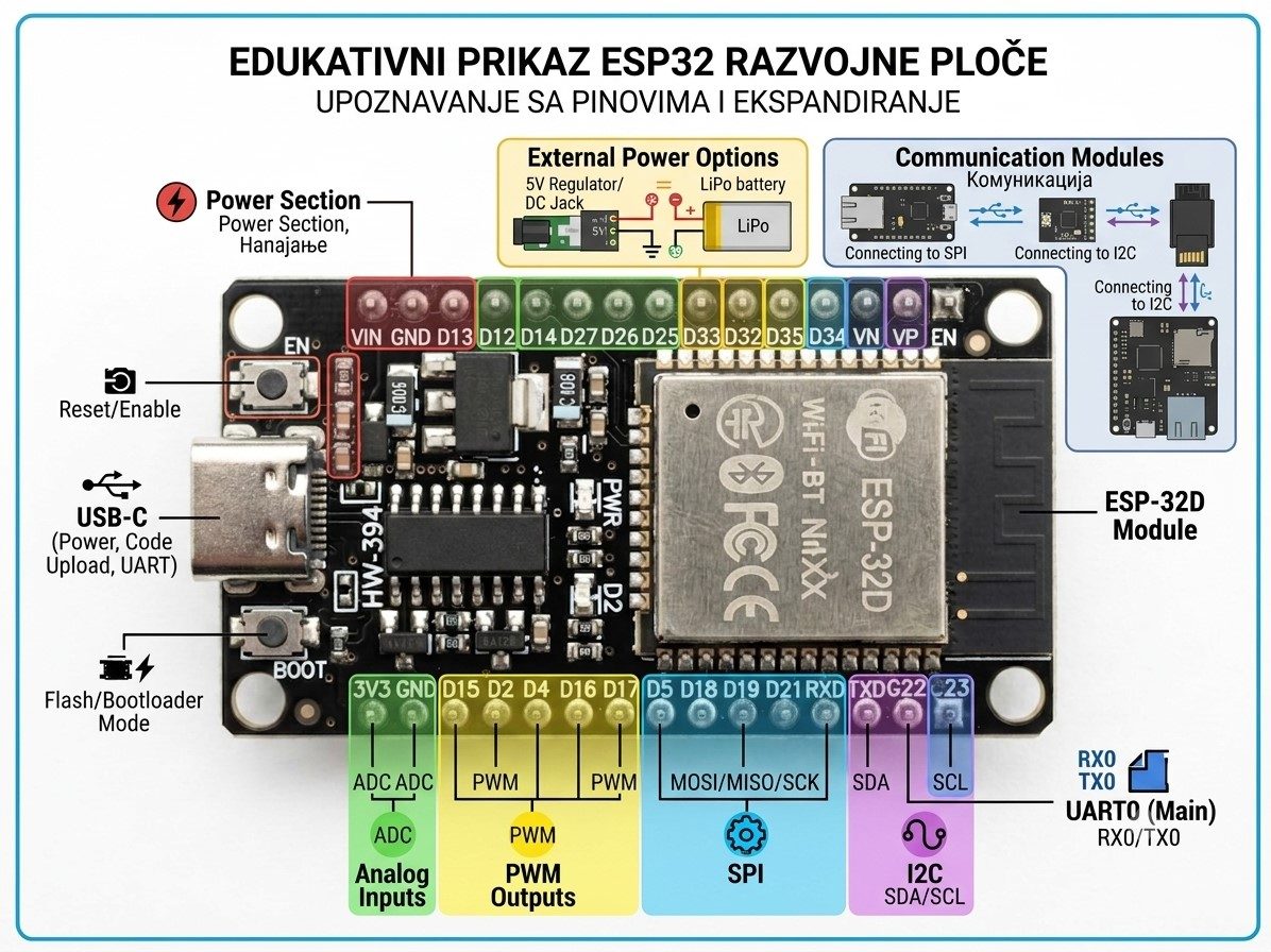
| Pins | Used for | Watch out |
|---|---|---|
| GPIO2 | built-in blue LED (on most boards) | – |
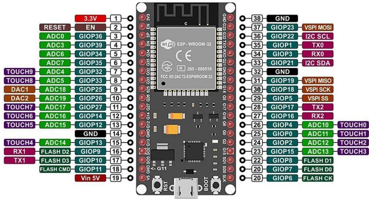
| GPIO4, 5, 13, 16–19, 21–23, 25–27, 32, 33 | digital inputs and outputs, PWM | 21 and 22 are I2C (SDA, SCL) |
| GPIO34, 35, 36, 39 | inputs only (analog input ADC1) | no output and no INPUT_PULLUP |
| GPIO0, 2, 12, 15 | work, but affect booting | do not connect buttons to GND on them at power-up |
| GPIO6–11 | used by the flash memory | do not use them |
Program 1: blinking LED
The built-in LED is on GPIO2, so you do not need to connect anything for the first program. For an external LED: the long leg (anode) through a 220 Ω resistor to GPIO2, the short leg to GND.
// ESP32 – first program: blinking an LED
const int LED_PIN = 2;          // built-in blue LED on most DevKit boards (GPIO2)

void setup() {
  pinMode(LED_PIN, OUTPUT);     // the pin is an output
  Serial.begin(115200);         // the ESP32 usually works at 115200 baud
  Serial.println("Blinking starts!");
}

void loop() {
  digitalWrite(LED_PIN, HIGH);  // on (3.3 V on the pin)
  delay(500);
  digitalWrite(LED_PIN, LOW);   // off (0 V)
  delay(500);
}
Open the Serial Monitor and set the speed to 115200 – the message from setup() is there. If you see "strange characters", the monitor speed is not the same as in Serial.begin().
Program 2: button
Connect the button between GPIO13 and GND, without a resistor: INPUT_PULLUP turns on a resistor inside the chip that keeps the pin HIGH. When we press the button, the pin is connected to GND and reads LOW.
// ESP32 – a button turns the LED on and off
const int LED_PIN = 2;
const int BUTTON_PIN = 13;      // button between GPIO13 and GND

bool ledOn = false;
int previous = HIGH;           // with INPUT_PULLUP: not pressed = HIGH

void setup() {
  pinMode(LED_PIN, OUTPUT);
  pinMode(BUTTON_PIN, INPUT_PULLUP);   // built-in resistor to 3.3 V
  Serial.begin(115200);
}

void loop() {
  int now = digitalRead(BUTTON_PIN);
  // react only at the moment of pressing (HIGH -> LOW)
  if (previous == HIGH && now == LOW) {
    ledOn = !ledOn;
    digitalWrite(LED_PIN, ledOn ? HIGH : LOW);
    Serial.println(ledOn ? "LED: on" : "LED: off");
    delay(30);                  // short pause against contact "bounce"
  }
  previous = now;
}
The program remembers the previous button state and reacts only to a change (HIGH → LOW). If we only wrote if (now == LOW), the LED would flicker while we hold the button.
Program 3: PWM – brightness
A pin can only be on or off. PWM (pulse-width modulation) switches it on and off thousands of times per second; if it is on most of the time, the LED looks brighter. On the Arduino this is analogWrite(), on the ESP32 the functions ledcAttach() and ledcWrite().
// ESP32 – PWM: the LED slowly fades in and out ("breathing")
// Arduino core 3.x: ledcAttach(pin, frequency, resolution) and ledcWrite(pin, value)
const int LED_PIN = 2;
const int FREQ = 5000;         // 5000 Hz – the eye cannot see flicker
const int RESOLUTION = 8;       // 8 bits: values from 0 to 255

void setup() {
  ledcAttach(LED_PIN, FREQ, RESOLUTION);
}

void loop() {
  for (int brightness = 0; brightness <= 255; brightness++) {   // brighter and brighter
    ledcWrite(LED_PIN, brightness);
    delay(8);
  }
  for (int brightness = 255; brightness >= 0; brightness--) {   // dimmer and dimmer
    ledcWrite(LED_PIN, brightness);
    delay(8);
  }
}
| Arduino Uno | ESP32 | |
|---|---|---|
| function | analogWrite(pin, 0–255) | ledcWrite(pin, value) |
| PWM pins | 6 pins (~) | almost all output pins |
| frequency | fixed (about 490 Hz) | we choose it (e.g. 5000 Hz) |
| resolution | 8 bits (0–255) | we choose it (1–14 bits) |
ledcAttach(pin, freq, res) you write ledcSetup(channel, freq, res) and ledcAttachPin(pin, channel), and ledcWrite takes the channel number. You can see the version in the Boards Manager.Program 4: potentiometer (analog input)
A potentiometer has three legs: the outer ones to 3V3 and GND, the middle one to GPIO34. The ESP32 has a 12-bit analog-to-digital converter: analogRead() returns a number from 0 to 4095 (on the Arduino Uno from 0 to 1023).
// ESP32 – a potentiometer sets the LED brightness
const int POT_PIN = 34;         // ADC1, input only
const int LED_PIN = 2;

void setup() {
  Serial.begin(115200);
  ledcAttach(LED_PIN, 5000, 8);
}

void loop() {
  int value = analogRead(POT_PIN);          // 0 .. 4095 (12-bit ADC)
  int brightness = map(value, 0, 4095, 0, 255); // convert to 0 .. 255
  ledcWrite(LED_PIN, brightness);
  Serial.print("ADC: ");
  Serial.print(value);
  Serial.print("  brightness: ");
  Serial.println(brightness);
  delay(100);
}
The map() function converts a number from one range to another: 0–4095 to 0–255. Note that the ESP32 analog input is not perfectly linear – near 0 V and 3.3 V the values "lag". That does not matter for this exercise.
Practice tasks
- Change program 1 so that the LED blinks twice quickly and then once slowly (like a heartbeat).
- Add a press counter to program 2 and print it in the Serial Monitor.
- Build a traffic light with three LEDs (GPIO 25, 26, 27, each with a 220 Ω resistor).
- Combine programs 2 and 3: each button press changes the LED brightness in a loop: 0, 64, 128, 255.
Solution: LED brightness in four steps
// the button changes the LED brightness: 0 -> 64 -> 128 -> 255 -> 0 ...
const int LED_PIN = 2;
const int BUTTON_PIN = 13;
const int LEVELS[4] = { 0, 64, 128, 255 };

int step = 0;
int previous = HIGH;

void setup() {
  pinMode(BUTTON_PIN, INPUT_PULLUP);
  ledcAttach(LED_PIN, 5000, 8);
  ledcWrite(LED_PIN, LEVELS[step]);
}

void loop() {
  int now = digitalRead(BUTTON_PIN);
  if (previous == HIGH && now == LOW) {
    step = (step + 1) % 4;          // after the last comes the first
    ledcWrite(LED_PIN, LEVELS[step]);
    delay(30);
  }
  previous = now;
}
Check your knowledge
Open the quiz
Quiz: ESP32 – LED, button and PWM
1. What is the highest voltage you may connect to an ESP32 pin?
2. What range does analogRead() return on the ESP32?
3. What does INPUT_PULLUP do?
4. Which functions change LED brightness on the ESP32 (package 3.x)?